Preliminar y, Mounting the mlc to an electrical box or mud ring, Conf ig ir extron mlc 226 ip – Extron Electronics MLC 226 IP Series Installation User Manual
Page 27: Extron mr 300, Confi g ir, Extron mlc 226 ip, Modular mud ring
2-17
MLC 226 IP Series • Installation
PRELIMINAR
Y
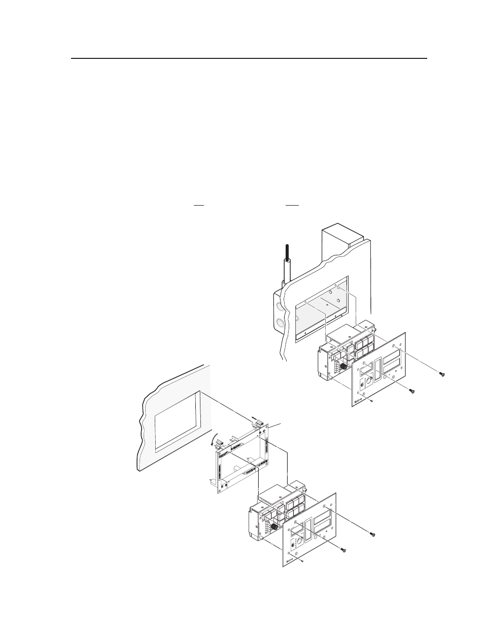
Mounting the MLC to an electrical box or mud ring
1.
With power disconnected at the source, insert the MLC into the wall or
furniture.
2.
Mount the MLC to the wall box or mud ring mounting bracket with the
provided machine screws (mounting screws, as shown in the following
illustrations).
N If the MLC (and any accessories such as control modules or an IR Link) is not
mounted to a grounded metal wall box,
• Ground each faceplate directly to an earth ground. Or...
• Tie each faceplate to its circuit board and power supply via a ground pin on
one of the connectors.
Do not tie a product’s faceplate to both a separate earth ground and the circuit
ground (via a connector pin). If you tie a product to two different ground
sources, you may introduce ground
loops or other grounding-
related problems into the
system.
N For the installation to
meet UL requirements
and to comply with
National Electrical Code
(NEC), the MLC must
be installed in a UL
approved junction box.
The end user or installer
must furnish the junction
box; it is not included
with the MLC.
OFF
ON
DOC
CAM
LAPT
OP
PC
VC
R
DV
D
PIC
MU
TE
AUT
O
IMA
GE
DI
SPLA
Y
1
2
3
4
5
6
VOL
UME
CONF
IG
IR
Extron
MLC 226 IP
ML
C 2
26
IP
Rotate locking
arm and insert
into wall
opening.
Extron
MR 300
Modular Mud Ring
Mounting the MLC to an electrical box or mud ring
3-gang Wall Box
OFF
ON
DOC
CAM
LAPT
OP
PC
VC
R
DVD
MUTE
PIC
MUTE
AUT
O
IM
AGE
DI
SP
LA
Y
1
2
3
4
5
6
VO
LU
ME
CONFI
G
IR
MLC
226
IP
Extron
MLC 226 IP
3-gang Wall Box
OFF
ON
DOC
CAM
LAPT
OP
PC
VC
R
DVD
MUTE
PIC
MUTE
AUT
O
IM
AGE
DI
SP
LA
Y
1
2
3
4
5
6
VO
LU
ME
CONFI
G
IR
MLC
226
IP
Extron
MLC 226 IP