Power connection, Preliminar y, Installation, cont’d – Extron Electronics MLC 226 IP Series Installation User Manual
Page 22
Installation, cont’d
MLC 226 IP Series • Installation
2-12
PRELIMINAR
Y
MLC/IR
A B C
MLS 506MA Rear Panel
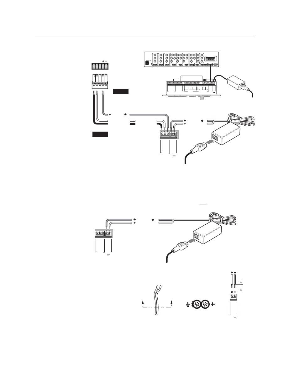
Connecting an MLC 226 IP
to a MediaLink Switcher and an external power supply
100-240V 0.2A 50/60 Hz
.5A MAX
INPUT 1
VIDEO
Y
C
R-Y
B-Y
YUV
Y
R-Y
B-Y
VIDEO
S-VIDEO
Y
C
INPUT 2
VIDEO
Y
C
R-Y
B-Y
INPUT 3
VIDEO
Y
C
R-Y
B-Y
INPUT 4
R
H/
HV
G
V
B
INPUT 5
R
H/
HV
G
V
B
INPUT 6
R
H/
HV
G
V
B
RGB
R
H/
HV
G
V
B
4 ohm
MONO AMPLIFIED OUTPUT
COMM
8 ohm
70V
L
R
L
R
L
R
L
R
AUX/MIX
EFFECTS
L
R
SEND
L
R
RETURN
MLC/IR
RS232
CONTACT CLOSURE
A B C
AUDIO OUT
FIXED
VARIABLE
L
R
L
R
L
L
R
R
L
R
MediaLink
Switcher's
rear panel
MLC/IR port
NOTE
You must connect
a ground wire
between the MLC
and MLS.
MLC's
MLS and
Power
ports
NOTE
If you use cable that
has a drain wire, tie
the drain wire to
ground at both
ends.
A B C D E
DISPLAY
RS-232/IR
RS-232 12V
CM/IR/SCP
A B C D E
MLS PWR
A B
Tx/IR
Rx
GR
OUND
PWR
S
N
S
GR
OUND
+12V OUT
Rx
Tx
GR
OUND
GR
OUND
+12V IN
+12V OUT
GR
OUND
CONT MOD
IR IN
S
CP COM
NORMALLY OPEN
1 2
COMMON
COMMON
COMMON
GR
OUND
Tx/IR
Tx/IR
Tx/IR
GR
OUND
GR
OUND
A
RELAYS
IR/SERIAL OUT
3 4
B
5 6
C
A
B
C
MLC 226 IP
Bottom Panel
RS-232 12V
MLS PWR
A B
Rx
Tx
GR
OUND
GR
OUND
+12V IN
Ground ( )
Transmit (Tx)
B
Receive (Rx)
A
Transmit (Tx)
Receive (Rx)
B
A
Ground ( )
+12 VDC input
Ground all devices.
External
Power Supply
(12 VDC, 1 A max.)
External
Power Supply
Power connection
f
PWR (power) connector — To provide power to the MLC, connect a cable
between this port and a 12 VDC, 1 amp (maximum) power supply. See the
following diagram.
N Power the controller via an external power supply, not from an Extron switcher.
The controller requires a separate 12 VDC power supply.
Connecting an MLC 226 IP to an external power supply
RS-232 12V
MLS PWR
A B
Rx
Tx
GR
OUND
GR
OUND
+12V IN
Ground ( )
+12 VDC input
Ground all devices.
External
Power Supply
(12 VDC, 1 A max.)
N Check the power supply’s
polarity before
connecting it
to the MLC.
See the
illustration at
right.
0.2”
(5 mm)
MAX.
MLC's
Power
Port
12V
PWR
GR
OUND
+12V IN
Power Supply Output Cord
End View of Power
Supply Output Cord
A
A
SECTION A–A
0.2”
(5 mm)
MAX.
MLC's
Power
Port
12V
PWR
GR
OUND
+12V IN
Power Supply Output Cord
End View of Power
Supply Output Cord
A
A
SECTION A–A