Preliminar y, Introduction, cont’d – Extron Electronics MLC 226 IP Series Installation User Manual
Page 10
Introduction, cont’d
MLC 226 IP Series • Introduction
1-4
PRELIMINAR
Y
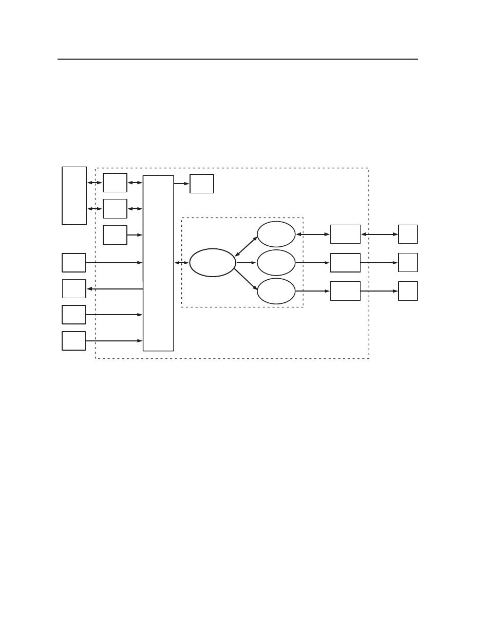
How the MLC 226 IP Series Controllers Work:
MLC Components and Interactions
Unlike the Extron MediaLink Controller (MLC 206 Series), the MLC 226 IP Series
requires and uses event fi les to perform all functions except basic input switching
and volume control. The event fi les defi ne, monitor, and govern how an MLC 226
IP Series controller works. Below is an example diagram of how the MLC interacts
with accessories, event scripts, drivers, ports, and input and output devices.
MAIN EVENT
(0.evt)
Host
Port
LAN
Port
Serial
Driver
RS-232
Proj Port
2-way
RS-232
Proj.
Proj. Driver
(4.evt)
MLC 226 IP
Firmware
FPC
FPC
Lights
Serial
Driver
IR/Serial
Port A
1-way
RS-232
DVD
DVD
Driver
(5.evt)
IR
Driver
IR/Serial
Port B
IR
Out
VCR
VCR Driver
(2.eir)
PC
with
Config.
Program
or
Web
Browser
MLC 226 IP
Memory
IR 402
Control
Modules
SCP
SCP
Lights
The MLC can be confi gured completely via the Extron Global Confi gurator
software. Once you have set up how you want it to work (assigned drivers to
ports, confi gured buttons and relays, and set up IP addresses and functions), that
information is saved to a project fi le that is uploaded into the MLC.
The confi guration information is used to create the “main event” (0.evt) script fi le
that defi nes the MLC’s operation. The main event fi le also controls and monitors
ports, optional SCP control pad(s), and changes made at the MLC’s front panel.
Each button on the MLC and on any connected SCPs, control modules (IRCMs,
ACMs, RCMs, CMs, DVCM), or the IR 402 remote control, has two switch numbers
assigned to it: one for the button press, one for release. Scripts are compiled to
generate the main event fi le to monitor any button press or release and to generate
the actions (issuing commands, triggering relays, switching inputs) associated with
the buttons.