Mlc 226 ip dv+ connections, Preliminar y, 9 mlc 226 ip series • installation – Extron Electronics MLC 226 IP Series Installation User Manual
Page 19: 1on 2 3 4
2-9
MLC 226 IP Series • Installation
PRELIMINAR
Y
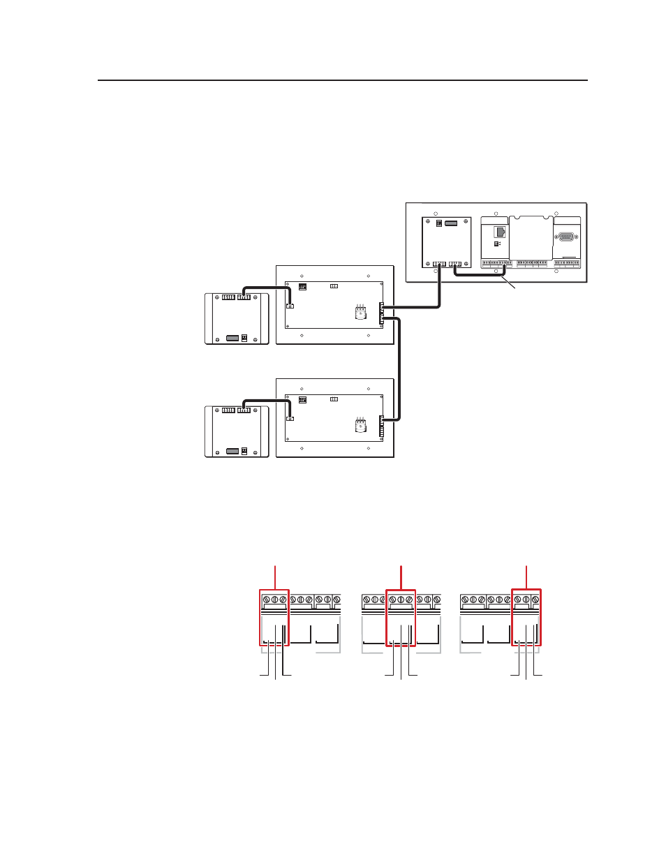
MLC 226 IP DV+ connections
The MLC 226 IP DV+ consists of an MLC 226 IP controller and an IRCM-DV+
installed in a high-impact plastic faceplate. The wiring is the same as in the
previous diagram, except the IRCM-DV+ is cabled to the MLC at the factory and
the IRCM-DV+ is the only type of control module that may be connected to each
SCP’s 3-pole connector. See the following diagram.
1
ON
2 3 4
J1
A
D
B C
E
A
D
B C
E
A
D
B C
E
A
D
B C
E
1
ON
2 3 4
J1
MLC 226 IP DV+ Rear Panel
SCP 226 Rear Panel
SCP 226 Rear Panel
IRCM-DV+
Rear Panel
IRCM-DV+
Rear Panel
HOST
CONTROL
PRESS TAB WITH
TWEEKER TO REMOVE
LAN
1=D INPUT I/O
2=Tx 3=Rx 5=GND
38400, N, 8, 1
R
INTERCOM
AU
D
IO
OUT
A
D
B
C
E
A
D
B
C
E
Factory-wired
MLC - to - IRCM-DV+
Connection
An MLC 226 IP DV+ with SCPs and additional control modules
c
Relay ports (24 V, 1 A) — These six relays allow control of items such as room
lighting, window coverings, and display screens. These contacts may be used
to control any equipment as long as the contact specifi cations of a total of
24 volts at 1 ampere are not exceeded for each port. The pin assignments are
shown in the following picture.
NORMALLY OPEN
1 2
COMMON
COMMON
COMMON
A
RELAYS
3 4
B
5 6
C
NORMALLY OPEN
1 2
COMMON
COMMON
COMMON
A
RELAYS
3 4
B
5 6
C
NORMALLY OPEN
1 2
COMMON
COMMON
COMMON
A
RELAYS
3 4
B
5 6
C
Group B
Group C
Group A
Common
Relay 4
Relay 3
Common
Relay 6
Relay 5
Common
Relay 2
Relay 1