GE Industrial Solutions CPS6000 User Manual
Page 91
CPS6000 –48V Indoor/Outdoor Power Shelf
Issue 21 January 2008
91
Connectors
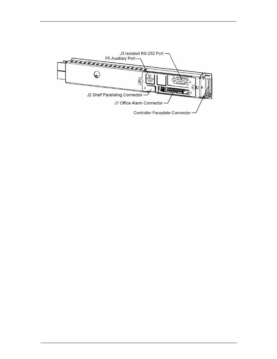
Figure 7-2 shows a side view of the controller unit.
Figure 7-2: QS840A Controller Unit Side View
An isolated RS-232 connector (J3) is provided for local access or for connection to an
external modem. The software interface is compatible with Lineage Power EasyView for
Windows GUI software for PCs. Software support is also provided for use with Lineage
Power Galaxy Manager for web-based remote access and monitoring.
The controller also includes six alarm relays. Two are pre-assigned as power Major and
power Minor alarm relays. The four remaining relays are available as user-definable alarms
and have been predefined for the various QS840A configurations.
Software
The software is functionally divided on the Main Menu into the following categories:
Alarms
Warnings
Status
Control/Operations
History
Configuration
The following figures show a map view of each category and the settings and operations
found in each, and are followed by brief descriptions of the menu items. Alarms and
Warnings are not hierarchal mapped and are presented in chronological order of occurrence
when they are present. “No Active Alarms” or “No Active Warnings” will be displayed when
they are no alarms or warnings detected by the controller.
Figures 7-3a through 7-3d provide a menu flow map of the QS840A controller software
followed by brief descriptions of the menu items. Older or customer controller may have only
some of the described menu items