GE Industrial Solutions CPS6000 User Manual
Page 156
CPS6000 –48V Indoor/Outdoor Power Shelf
Issue 21 January 2008
156
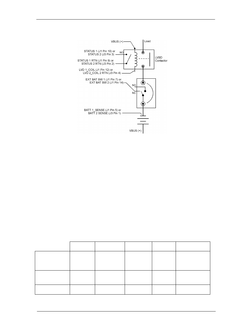
Figure 12-4: Reverse Polarity Protected Alarm Connections with an
External Battery Disconnect Switch
Figure 12-4 shows the connections required if Reverse Polarity Protection is to be used with
an external disconnect switch. Note that the sense lead BATT1_SENSE or BATT2_SENSE
must be connected as shown in order for the reverse polarity protection feature to work. If
two strings are being used, connect one string to STATUS1, LVD1_COIL, STATUS1_RTN,
BATCB1, and BATT1_SENSE connections and the other to the "-2" connections. When
more than two strings are being used, divide the strings among the two inputs.
WARNING
When two battery strings are connected to the same battery terminal, care must be
taken to ensure the polarity of the two strings is correct to each other. Improper
connection will result in one string being shorted to the other string and the system can
not protect against this.
With the above connections, the following alarms will be issued for the conditions noted. This
assumes the external disconnect switch is used to open and close the battery charging path to
the batteries.
Contactor
Fail Alarm
Contactor
Open Alarm
Open String
Alarm
QS840A
LED ES772
LED
Open Integral
ES772A
Disconnect
Switch
X
RED
Blinking
AMBER
Battery
reconnected in
reverse polarity
X X
RED
RED
System started w/
reverse battery
X X
RED
RED