GE Industrial Solutions CPS6000 User Manual
Page 171
CPS6000 –48V Indoor/Outdoor Power Shelf
Issue 21 January 2008
171
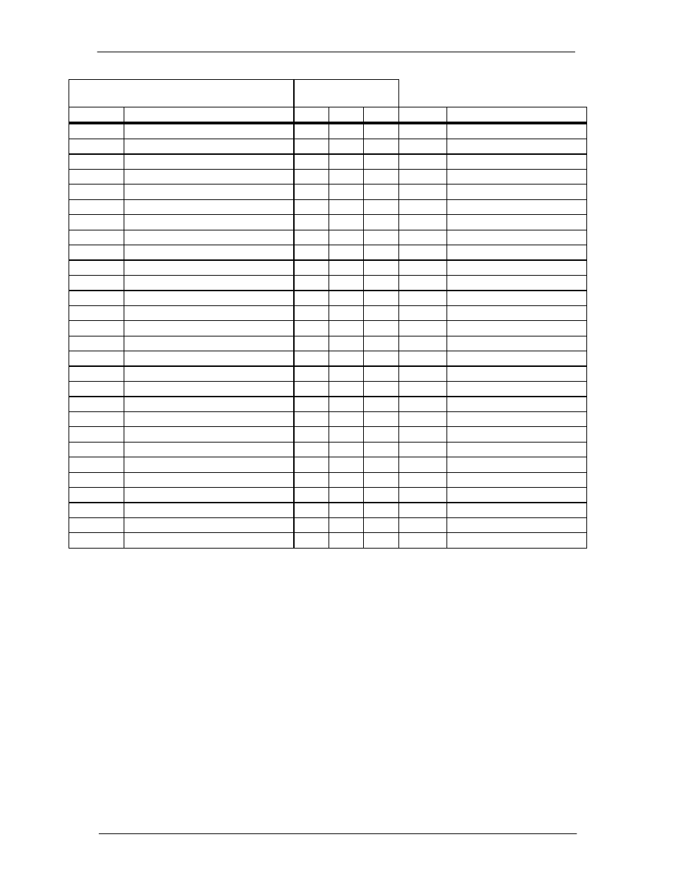
Alarm Thresholds/Relays
Related Commands
obj,attr
description sta
cha
ope
type
range
of
values
macf1,sev Multiple AC fail severity
x x
text “MAJ”, “MIN” , or “RO"
mcm1,acc Major
communication
relay
x x
text
“R1” ,“R2”, “R3”, “R4”, or “”
mcm1,ast Major
communication
alarm
state
x
number 0:not
active
1:active
mcm1,sev Major
communication
severity
x x
text “MAJ”, “MIN” , or “RO"
mrfa1,acc Multiple rectifier fail relay
x x
text
“R1” ,“R2”, “R3”, “R4,” or “”
mrfa1,ast Multiple rectifier fail alarm state
x
number 0:not
active
1:active
mrfa1,sev Multiple rectifier fail severity
x x
text “MAJ”, “MIN” , or “RO"
osa1,acc
Open string alarm relay
x x
text
“R1” ,“R2”, “R3”, “R4”, or “”
osa1,ast
Open string alarm state
x
number 0:not
active
1:active
osa1,sev
Open string alarm severity
x x
text “MAJ”, “MIN” , or “RO"
rfa1,acc
Rectifier fail relay
x x
text
“R1” ,“R2”, “R3”, “R4”, or “”
rfa1,ast
Rectifier fail alarm state
x
number 0:not
active
1:active
rfa1,sev
Rectifier fail severity
x x
text “MAJ”, “MIN” , or “RO"
rls1,acc
Rectifier redundancy loss relay
x x
text
“R1” ,“R2”, “R3”, “R4”, or “”
rls1,ast
Rect redundancy loss alarm state
x
number 0:not
active
1:active
rls1,sev
Rect redundancy loss severity
x x
text “MAJ”,
“MIN” , or “RO"
scd1,acc
Battery voltage imbalance relay
x x
text
“R1” ,“R2”, “R3”, “R4”, or “”
scd1,ast
Battery voltage imbalance alarm state
x
number 0:not
active
1:active
scd1,sev
Battery voltage imbalance severity
x x
text “MAJ”, “MIN” , or “RO"
tpa1,acc
Thermal probe fail relay
x x
text
“R1” ,“R2”, “R3”, “R4”, or “”
tpa1,ast
Thermal probe fail alarm state
x
number 0:not
active
1:active
tpa1,sev
Thermal probe fail severity
x x
text “MAJ”,
“MIN” , or “RO"
vmf1,acc Voltage module fail relay
x x
text
“R1” ,“R2”, “R3”, “R4”, or “”
vmf1,ast
Voltage module fail alarm state
x
number 0:not
active
1:active
vmf1,sev Voltage module fail severity
x x
text “MAJ”,
“MIN” , or “RO"
vsf1,acc
Sense voltage fail relay
x x
text
“R1” ,“R2”, “R3”, “R4”, or “”
vsf1,ast
Sense voltage fail alarm state
x
number 0:not
active
1:active
vsf1,sev
Sense voltage fail severity
x x
text “MAJ”, “MIN” , or “RO"
The previous table outlines the various alarms that are available through the QS840A
controller. Refer to Alarm Relays in Appendix C for more details. The QS840A
controller is provided with two severity relays and two relays that may be assigned to
any combination or all of the alarms noted above.
The controller is shipped with PMN assigned to Alarm Relay 2 and PMJ to Alarm
Relay 1. Also, for each alarm condition noted above, the factory severity is noted in
bold. The user may change the severity of configurable alarms from the factory set
severity. Note that the alarms noted above may also be assigned a severity of RO
(Record Only). If so assigned, the alarm condition will be transmitted without any
PMJ or PMN severity.