GE Industrial Solutions CPS6000 User Manual
Page 200
CPS6000 –48V Indoor/Outdoor Power Shelf
Issue 21 January 2008
200
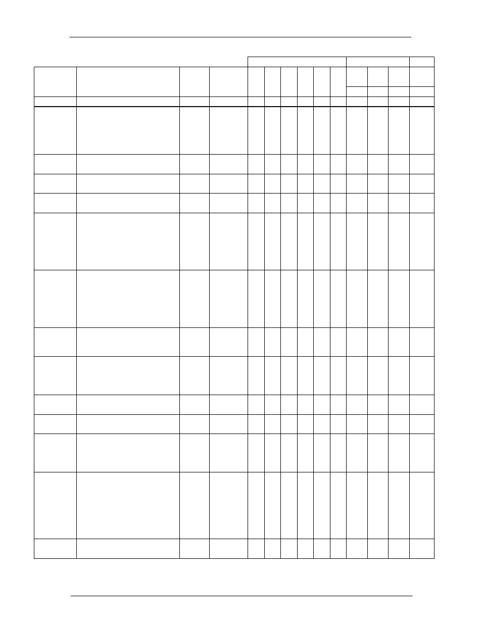
Alarm Relays
LED
LED
Alarm / Event
Description
Default
Setting
Range /
Severity
PMJ PMN Relay
1
Relay
2
Relay
3
Relay
4
PMJ PMNNORM AUXMD
Red Yellow Green
Red
Open
intervention or LVD disconnect.
Manual Or
Periodic Battery
Test In Progress
Condition asserted to provide a remote
indication that a battery test has been
initiated either through automatic
means. Automatic testing must be
enabled. Factory default is disabled.
RO Major/
Minor/RO
o
Monitoring
Module Failure
Controller has detected a failure in an
attached remote monitoring module.
Minor Major/
Minor/RO
x
x
Multiple AC
Fail
Detection of two or more rectifiers
reporting ACF in the system.
Major Major/
Minor/RO
x
o
x
Multiple
Rectifier Fail
Detection of two or more rectifiers
failing in the system.
Major Major/
Minor/RO
x
o
x
Open String
Alarm issued when an external
disconnect switch produces an open
charge path to batteries in the
Distribution Module. This alarm is only
available when used with the QS872A
Board is in the system (connector P4).
Major Major/
Minor/RO
x
x
Rectifier
Redundancy
Loss
Alarm asserted when the total rectifier
output current exceeds N rectifier
capacity value. The feature must be
enabled and assumes N+1 rectifiers are
present in the system. Disabled by
default.
Disabled/
Minor
Enabled/
Disabled
(Major/
Minor/RO)
x
x
Reserve Time
Low
Reserve time low alarm threshold
configured for systems calculated back-
up reserve has been reached.
0 hours
Minor
0-99.9 hours
Major/
Minor/RO
x
x
Sense Fuse
Alarm that is automatically asserted
when the controller senses the DC bus
voltage to be lower than 35.5V +/-
0.5V.
Major Major/
Minor/RO
x
x
Single AC Fail Detection of a single rectifier reporting
ACF in the system.
Minor
Major/
Minor/RO
x
o
x
Single Rectifier
Fail
Detection of a single rectifier failing in
the system.
Minor
Major/
Minor/RO
x
o
x
Un-powered
Controller
The controller is not receiving DC
power from the shelf. All Form-C relays
are de-energized to assert respective
alarms.
N/A
N/A
x
x
x
x
x
x
Very Low Float
Voltage
The system DC output voltage has
reached a low voltage threshold
generally set below the BD threshold.
This alarm is used to indicate that the
battery reserve is depleting and the DC
voltage is approaching a critically low
output value.
46.0V
Major
40-51V
Major/
Minor/RO
x
x
Voltage
Imbalance
Alarm asserted when the controller
detects greater than 1.7V difference
Disabled/
Major
Enabled/
Disabled
x
x