GE Industrial Solutions CPS6000 User Manual
Page 153
CPS6000 –48V Indoor/Outdoor Power Shelf
Issue 21 January 2008
153
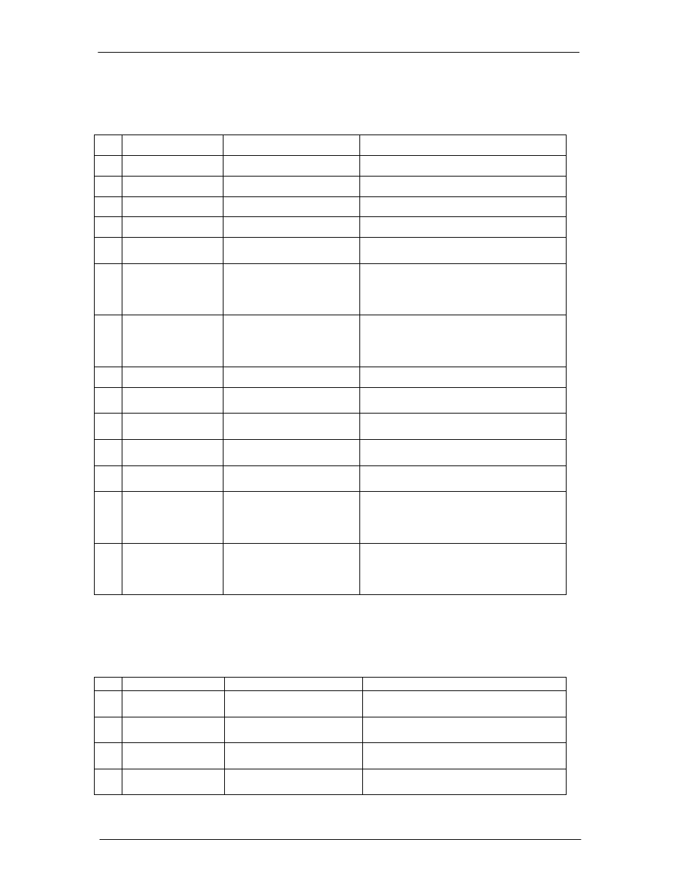
The following tables provide the pin-out definitions for J1 and J3.
Table 12-A: Connector J1 Pin-out Definitions
Pin Name
Definition
Comments/Connections
1
VPWR +
V(+) Power
Power for ES772A, connect to VBus(+)
2 N/A
Reserved
3 N/A
Reserved
4
SHUNT-
Neg Batt Shunt Input
Polarity is during battery discharge
5
BATT1_SENSE
Polarity Sense for String 1
Connect to battery negative, V(-) of String
1
6 DIST_ALM_1
Trip-Indicator
Input-1
for
US Style CB or GMT Fuse.
Alarm on closure to VBus(-
).
Connect to NC terminal of breaker micro
switch or to indicator lead of GMT fuse,
other end (C) referenced to VBus(-).
7
EXT BAT SW1
Alarm input for external
battery disconnect switch;
alarm on closure to VBus(-
).
Connect to NC micro switch of US Style
CB, other end (C) referenced to VBus(-),
micro switch must close upon manual
opening of CB.
8
VPWR -
V(-) Power
Power for ES772A, connect to VBus(-)
9
STATUS1_RTN
Reference for STATUS1
Connect to C pin of micro switch of
Contactor 1.
10 STATUS1
Contactor 1 Status Monitor
Connect to NO pin of micro switch of
Contactor 1.
11 SHUNT+
Positive Battery Shunt
Input
Polarity is during battery discharge
12 LVD1_COIL
Contactor 1 coil input
Connect to one side of Contactor 1 coil,
other side of coil connected to VBus(+).
13 DIST_ALM_2
Trip-Indicator
Input-2
for
US Style CB or GMT Fuse.
Alarm on closure to VBus(-
).
Connect to NC terminal of breaker micro
switch or to indicator lead of GMT fuse,
other end (C) referenced to VBus(-).
14 EXT BAT SW2
Alarm input for external
battery disconnect switch;
alarms on closure to
VBus(-).
Connect to NC micro switch of US Style
CB, other end (C) referenced to VBus(-),
micro switch must close upon manual
opening of CB.
Table 12-B: Connector J3 Pin Definitions
Pin Name
Definition
Comments
1
BATT2_SENSE
Polarity Sense for String 2.
Connect to battery negative VBus(-) of
string 2.
2
STATUS2_RTN
Reference for STATUS2.
Connect to C pin of micro switch of
Contactor 2.
3
STATUS2
Contactor 2 Status Monitor. Connect to NO pin of micro switch of
Contactor 2.
4
LVD2_COIL
Contactor 2 coil input.
Connect to one side of Contactor 2 coil,
other side of coil connected to VBus(+).