Distribution module gmt fuses – GE Industrial Solutions CPS6000 User Manual
Page 28
CPS6000 –48V Indoor/Outdoor Power Shelf
Issue 21 January 2008
28
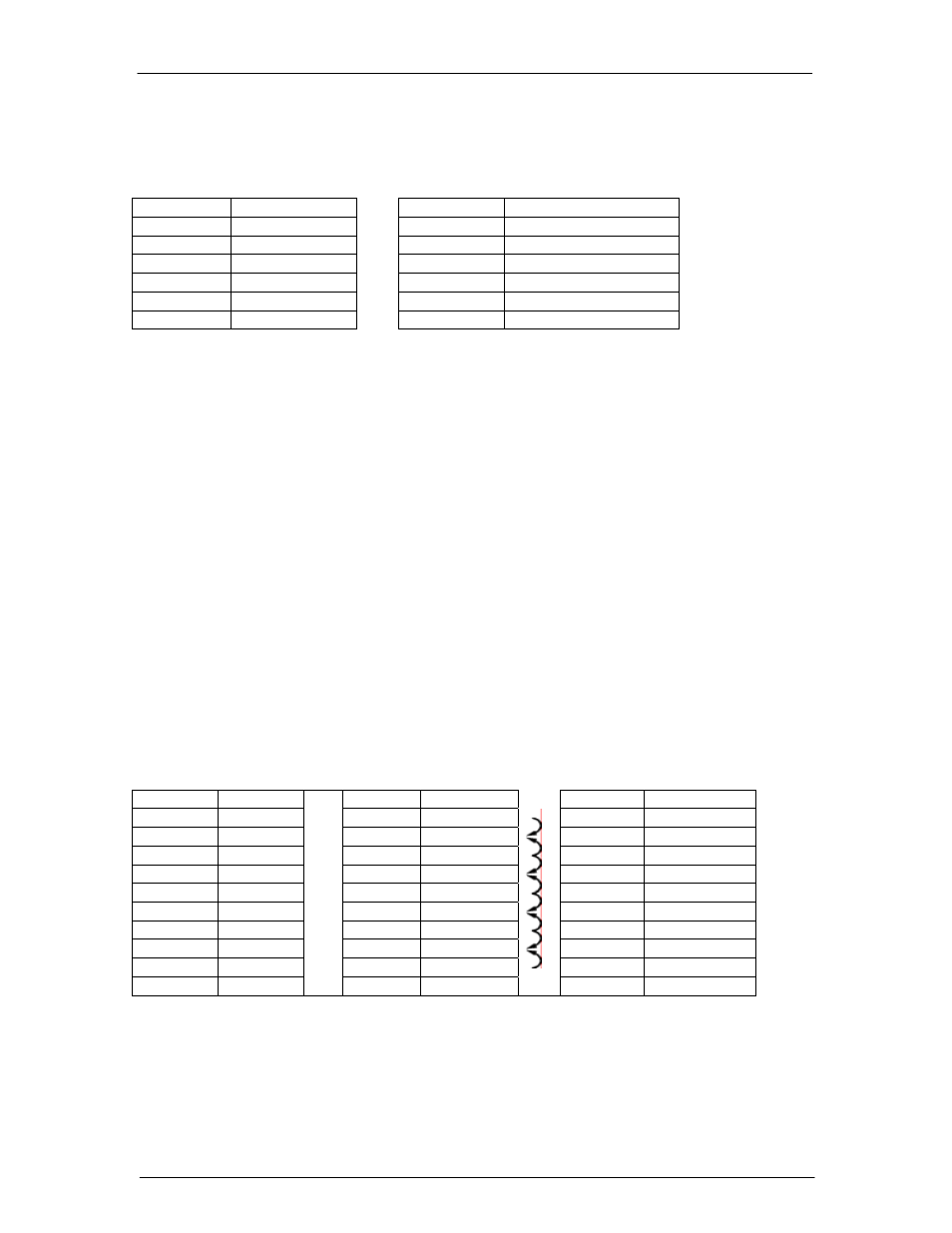
Distribution Module GMT Fuses
The following GMT fuses have been accepted for use in dc load applications, are available
for the current Distribution Module.
Size (Amps)
Comcode
Size (Amps)
Comcode
0.25 405006222
7.5
405725433
0.5 406976894
10
406159236
1.33 405673146
12
407845197
2 405181983
15
406473959
3 406976985
20
408555453
5 406159061
The following shows the possible fuse loading scenario for the Single-Slot and Double-Slot
Distribution Modules. 20A fuse positions can be used only with factory wiring. When using
20A fuses, adjacent fuse positions must be left open.
For the Single-Slot Distribution Module with 10 GMT fuses, Field installation is only rated
for 10A fuses. No more than 80A may be carried through the 10 fuse positions, or 40A
through each half section. 15A and lower rated fuses may be used in any combination and
position, as long as they do not violate the previous 80A/40A rule.
For the Single-Slot Distribution Module with 5 GMT fuses, a maximum load of 32 A is
permitted with restrictions on the fuse positions. Specifically:
Position F1 defined
as the bottom fuse position and F5 as the top fuse position.
1. Configuration #1 - F1+F2 <= 15A, F3<=
1
5A, and F5+F4<= 10A
2. Configuration #2 - F1<=15A; F2=No Fuse; F3<=15A; F4=No Fuse; F5<=10A 3.
For the Double-Slot Distribution Module, each 8-fuse board can support a maximum of 80A.
Single-Slot Distribution Module
Double-Slot
Distribution Module
Position
Max Fuse
Position
Max Fuse
Position
Max Fuse
10
10
15A
8
15A/20A
9 20A
9
7
8
8
15A
6
15A/20A
7 20A
7
5
6
6
15A
4
15A/20A
5
5
3
4 20A
4 15A
2 15A/20A
3
3
1
2 20A
2 15A
1
1
15A
(Arrows indicate
alternate positions)