GE Industrial Solutions CPS6000 User Manual
Page 61
CPS6000 –48V Indoor/Outdoor Power Shelf
Issue 21 January 2008
61
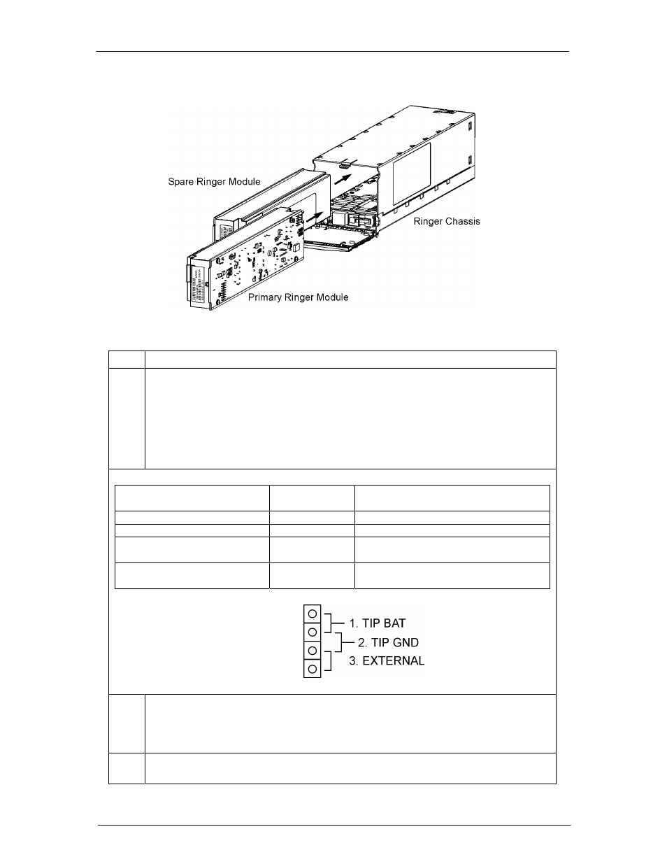
Figure 5-17: Ringer Installation
Step Action
7.
Use Tip Jumper J12 to set the Ringer output type. See Figure 5-16 for J12 Tip
Jumper location.
Note: Ringer output type is determined by connecting Ring Return (Tip) to Battery
or Ground. External connection of Ring Return (TIP) to Battery or Ground may be
used with J12 in EXTERNAL position. Ringer output is disabled if Ring Return is
not connected to Battery or to ground. See Section 10 for more information on
Ringing Types.
Ringing Type
Tip Jumper
J12 Position
Comments
Ground Backed
1. TIP BAT
Battery Backed
2. TIP GND
Ground Backed – no-dc
2. TIP GND
Also requires Controller configuration of
dc Offset: Disabled
Externally Selected
3. EXTERNAL
Requires external connection of Tip to
Battery or Ground.
8.
Warning: Consider the Ring signal as hazardous voltage.
Connect Ringer loads using Molex 39-01-4031 connector, Socket Terminal to the
HDR13 plug located inside the Ringer Chassis at the bottom-front. See Figure 5-
18.
9.
Route ringer load cables through upper or lower notches in Ringer chassis and
distribution module chassis. See Figure 5-18.