Rainbow Electronics DS2152 User Manual
Page 58
DS2152
031897 58/79
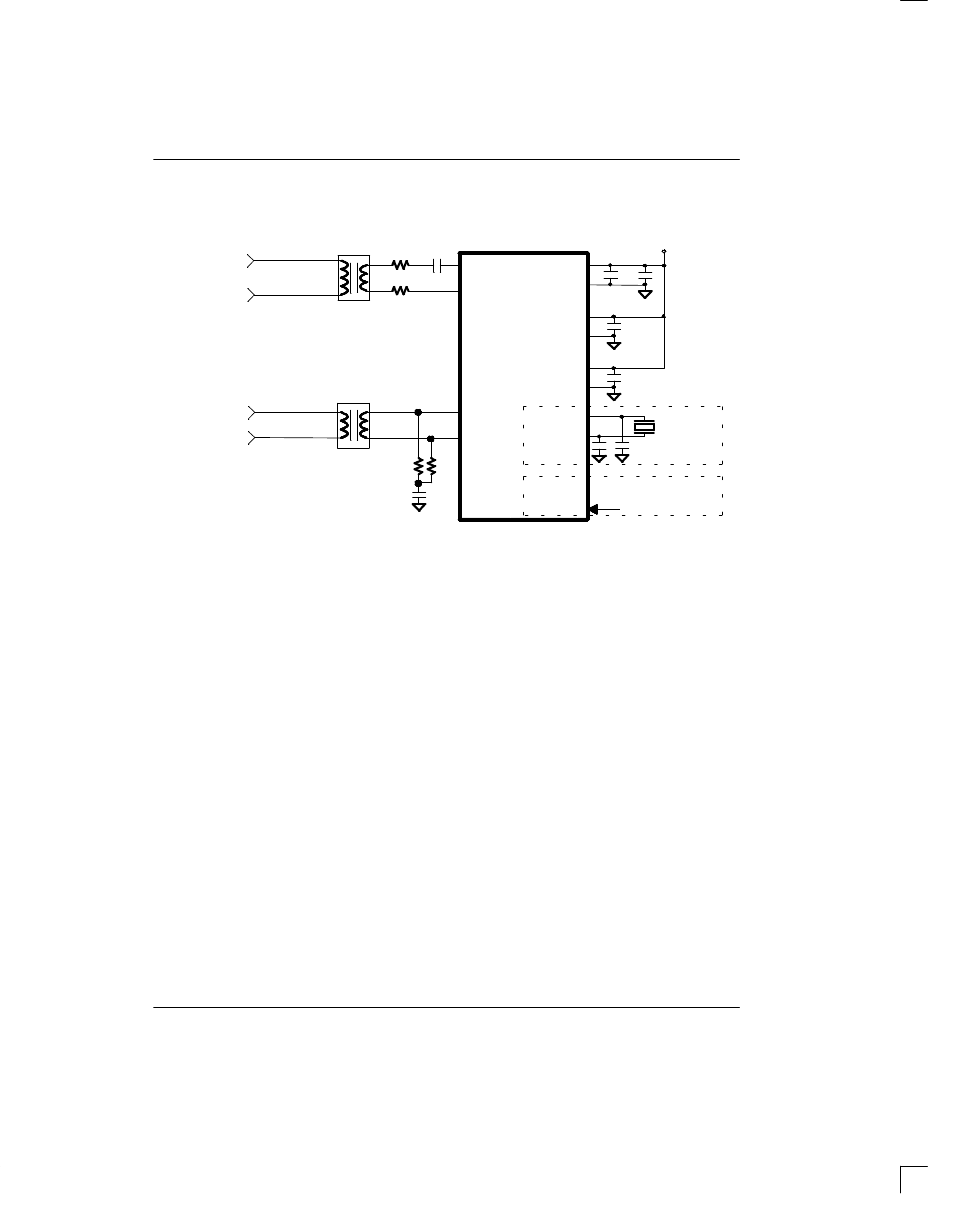
DS2152 EXTERNAL ANALOG CONNECTIONS Figure 14–1
1:1
1.15:1 (Rt = 0 Ohms) or
1.36:1 (Rt = 4.7 Ohms)
(larger winding toward
0.47 uF
(non–
polarized)
0 . 1 u F
0 . 1 u F
0 . 1 u F
+ 5 V
50
50
0.1 uF
Rt
Rt
0 . 0 1 u F
1.544 MHz
–or–
C1/C2
61
60
18
19
31
30
DS2152
T1 TRANSMIT
LINE
T1 RECEIVE
LINE
TTIP
TRING
RTIP
RRING
DVDD
DVSS
RVDD
RVSS
TVDD
TVSS
XTALD
MCLK
MCLK
XTALD
the network)
1.544 MHz
NOTES:
1. Resistor values are
±
1%.
2. The Rt resistors are used to protect the device from over–voltage.
3. See the Separate Application Note for details on how to construct a protected interface.
4. Either a crystal can be applied across the MCLK and XTALD pins or a TTL level clock can be applied to just
MCLK.
5. C1 and C2 should be 5 pF lower than two times the nominal loading capacitance of the crystal to adjust for
the input capacitance of the DS2152.
- MAX12005 (14 pages)
- MAX7058 (14 pages)
- MAX9995 (13 pages)
- MAX7034 (13 pages)
- MAX7033 (16 pages)
- MAX9476 (8 pages)
- MAX9486 (8 pages)
- MAX14821 (29 pages)
- MAX9489 (11 pages)
- MAX9491 (11 pages)
- DS2130Q (22 pages)
- DS21458 (270 pages)
- DS3131 (174 pages)
- DS26502 (125 pages)
- DS2153Q (48 pages)
- DS26503 (123 pages)
- DS2186 (11 pages)
- DS1842A (6 pages)
- DS3134 (203 pages)
- DS1876 (69 pages)
- DS1874 (88 pages)
- DS31256 (181 pages)
- DS2141A (35 pages)
- DS3184 (13 pages)
- DS2154 (69 pages)
- DS26504 (128 pages)
- DS3164 (12 pages)
- DS1852 (25 pages)
- DS2181A (32 pages)
- DS2151Q (46 pages)
- DS1843 (8 pages)
- DS2165Q (17 pages)
- DS3170 (233 pages)
- DS2180A (36 pages)
- DS2172 (20 pages)
- DS1841 (16 pages)
- DS2182A (22 pages)
- DS2143Q (40 pages)
- DS2132A_Q (17 pages)
- DS1862 (42 pages)
- DS26519 (310 pages)
- DS2188 (11 pages)
- DS1875 (92 pages)
- DS33M33 (20 pages)