Rainbow Electronics DS2152 User Manual
Page 52
DS2152
031897 52/79
11.2.3 Transmit Section
The transmit section will shift out into the T1 data
stream, either the FDL (in the ESF framing mode) or the
Fs bits (in the D4 framing mode) contained in the Trans-
mit FDL register (TFDL). When a new value is written to
the TFDL, it will be multiplexed serially (LSB first) into
the proper position in the outgoing T1 data stream. After
the full eight bits has been shifted out, the DS2152 will
signal the host microcontroller that the buffer is empty
and that more data is needed by setting the SR2.3 bit to
a one. The INT will also toggle low if enabled via
IMR2.3. The user has 2 ms to update the TFDL with a
new value. If the TFDL is not updated, the old value in
the TFDL will be transmitted once again.
The DS2152 also contains a zero stuffer which is con-
trolled via the CCR2.4 bit. In both ANSI T1.403 and
TR54016, communications on the FDL follows a subset
of a LAPD protocol. The LAPD protocol states that no
more than 5 ones should be transmitted in a row so that
the data does not resemble an opening or closing flag
(01111110) or an abort signal (11111111). If enabled via
CCR2.4, the DS2152 will automatically look for 5 ones
in a row. If it finds such a pattern, it will automatically
insert a zero after the five ones. The CCR2.0 bit should
always be set to a one when the DS2152 is inserting the
FDL. More on how to use the DS2152 in FDL applica-
tions is covered in a separate Application Note.
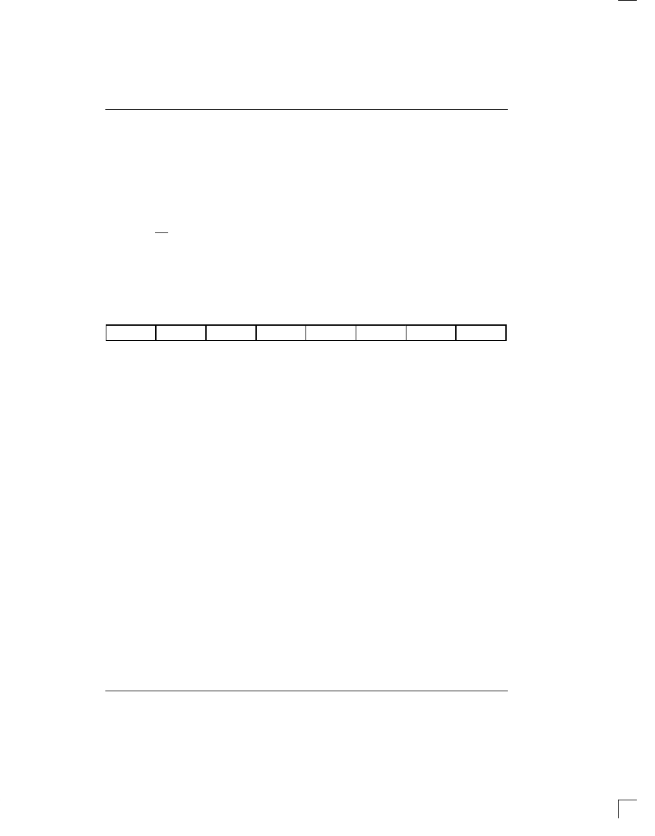
TFDL: TRANSMIT FDL REGISTER (Address=7E Hex)
[also used to insert Fs framing pattern in D4 framing mode; see Section 11.3]
(MSB)
(LSB)
TFDL7
TFDL6
TFDL5
TFDL4
TFDL3
TFDL2
TFDL1
TFDL0
SYMBOL
POSITION
NAME AND DESCRIPTION
TFDL7
TFDL.7
MSB of the FDL code to be transmitted
TFDL0
TFDL.0
LSB of the FDL code to be transmitted
The Transmit FDL Register (TFDL) contains the Facility Data Link (FDL) information that is to be inserted on a byte
basis into the outgoing T1 data stream. The LSB is transmitted first.
11.3 D4/SLC–96 OPERATION
In the D4 framing mode, the DS2152 uses the TFDL
register to insert the Fs framing pattern. To allow the
device to properly insert the Fs framing pattern, the
TFDL register at address 7Eh must be programmed to
1Ch and the following bits must be programmed as
shown:
TCR1.2=0 (source Fs data from the TFDL
register)
CCR2.5=1 (allow the TFDL register to load on
multiframe boundaries)
Since the SLC–96 message fields share the Fs–bit posi-
tion, the user can access the these message fields via
the TFDL and RFDL registers. Please see the separate
Application Note for a detailed description of how to
implement a SLC–96 function.
12.0 PROGRAMMABLE IN–BAND CODE
GENERATION AND DETECTION
The DS2152 has the ability to generate and detect a
repeating bit pattern that is from one to eight bits in
length. To transmit a pattern, the user will load the pat-
tern to be sent into the Transmit Code Definition (TCD)
register and select the proper length of the pattern by
setting the TC0 and TC1 bits in the In–Band Code Con-
trol (IBCC) register. Once this is accomplished, the pat-
tern will be transmitted as long as the TLOOP control bit
(CCR3.1) is enabled. Normally (unless the transmit for-
matter is programmed to not insert the F–bit position)
the DS2152 will overwrite the repeating pattern once
every 193 bits to allow the F–bit position to be sent. See
Figure 15–11 for more details. As an example, if the
user wished to transmit the standard “loop up” code for
Channel Service Units which is a repeating pattern of
...10000100001... then 80h would be loaded into TDR
and the length would set to 5 bits.
The DS2152 can detect two separate repeating pat-
terns to allow for both a “loop up” code and a “loop down”
code to be detected. The user will program the codes to
be detected in the Receive Up Code Definition
(RUPCD) register and the Receive Down Code Defini-
tion (RDNCD) register and the length of each pattern will