Installation guide, E8950 – Veris Industries E8950 Install User Manual
Page 32
TM
E8950
INSTALLATION GUIDE
ZL0105-0B
PAGE 32
©2013 Veris Industries USA 800.354.8556 or +1.503.598.4564 / [email protected]
02131
Alta Labs, Enercept, Enspector, Hawkeye, Trustat, Aerospond, Veris, and the Veris ‘V’ logo are trademarks or registered trademarks of Veris Industries, L.L.C. in the USA and/or other countries.
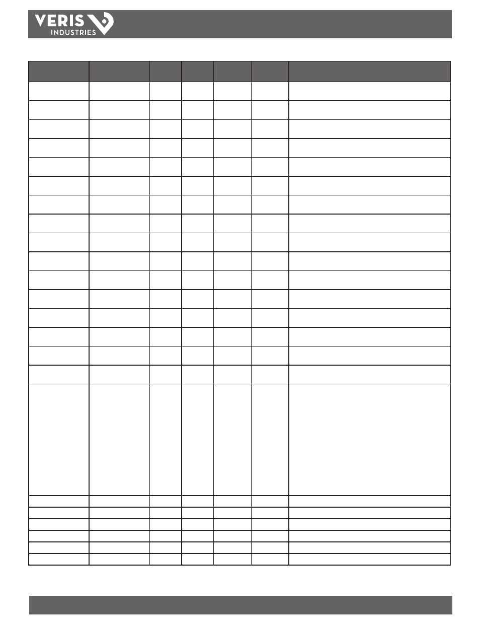
Data Variable
Description
BACnet
Object
Units
COV_
Increment
Modbus
Address
Comments
Amps: Phase 4 (Neutral) Instantaneous Neutral
Current
AI23
Amps
5
644/645
Amps Present Demand:
Phase 1
Present Current
Demand- Phase 1
AI24
Amps
5
646/647
Amps Present Demand:
Phase 2
Present Current Demand
- Phase 2
AI25
Amps
5
648/649
Amps Present Demand:
Phase 3
Present Current Demand
- Phase 3
AI26
Amps
5
650/651
Amps Present Demand:
(Neutral)
Present Current Demand
- Neutral
AI27
Amps
5
652/653
Amps Max Demand:
Phase 1
Max Current Demand -
Phase 1
AI28
Amps
5
654/655
Amps Max Demand:
Phase 2
Max Current Demand -
Phase 2
AI29
Amps
5
656/657
Amps Max Demand:
Phase 3
Max Current Demand -
Phase 3
AI30
Amps
5
658/659
Amps Max Demand:
(Neutral)
Max Current Demand -
Neutral
AI31
Amps
5
660/661
kW Present Demand:
3ph Total
Real Power Present
Demand - 3ph Total
AI32
kW
1
662/663
kW Max Demand: 3ph
Total
Real Power Max Demand
- 3ph Total
AI33
kW
1
664/665
Max Amps: Phase 1
Max Instantaneous
Current - Phase 1
AI34
Amps
5
666/667
Max Amps: Phase 2
Max Instantaneous
Current - Phase 2
AI35
Amps
5
668/669
Max Amps: Phase 3
Max Instantaneous
Current - Phase 3
AI36
Amps
5
670/671
Max Amps: (Neutral)
Max Instantaneous
Neutral Current
AI37
Amps
5
672/673
kW: 3ph Max
Max Instantaneous Real
Power- 3ph Total
AI38
kW
1
674/675
Device Health
Bit Map of Device Health
Indicators
AI39
n/a
1
532
Bit 0: Reserved
Bit 1: Frequency out of range or insufficient voltage on Phase A to
determine frequency range. Frequency range is 40-70 Hz.
Bit 2: Phase A Voltage Clipping
Bit 3: Phase B Voltage Clipping
Bit 4: Phase C Voltage Clipping
Bit 5: Current Clipping on at least 1 channel (AUX and Circuit)
Bit 6-7: Reserved
Bit 8: Strip Connection Error
Bit 9-12: Reserved
Bit 13: Current Model, Model C
Bit 14: Power Model, Model B
Bit 15: Branch Power, Model A
Reserved for future use
Reserved for future use
AI40
n/a
1
533
Reserved for future use
Reserved for future use
AI41
n/a
1
534
Reserved for future use
Reserved for future use
AI42
n/a
1
535
Reserved for future use
Reserved for future use
AI43
n/a
1
536
Reserved for future use
Reserved for future use
AI44
n/a
1
537
Reserved for future use
Reserved for future use
AI45
n/a
1
538
E30A042 and E30A142 Branch Circuit Power Meter, cont.