Installation guide, E8950 – Veris Industries E8950 Install User Manual
Page 18
TM
E8950
INSTALLATION GUIDE
ZL0105-0B
PAGE 18
©2013 Veris Industries USA 800.354.8556 or +1.503.598.4564 / [email protected]
02131
Alta Labs, Enercept, Enspector, Hawkeye, Trustat, Aerospond, Veris, and the Veris ‘V’ logo are trademarks or registered trademarks of Veris Industries, L.L.C. in the USA and/or other countries.
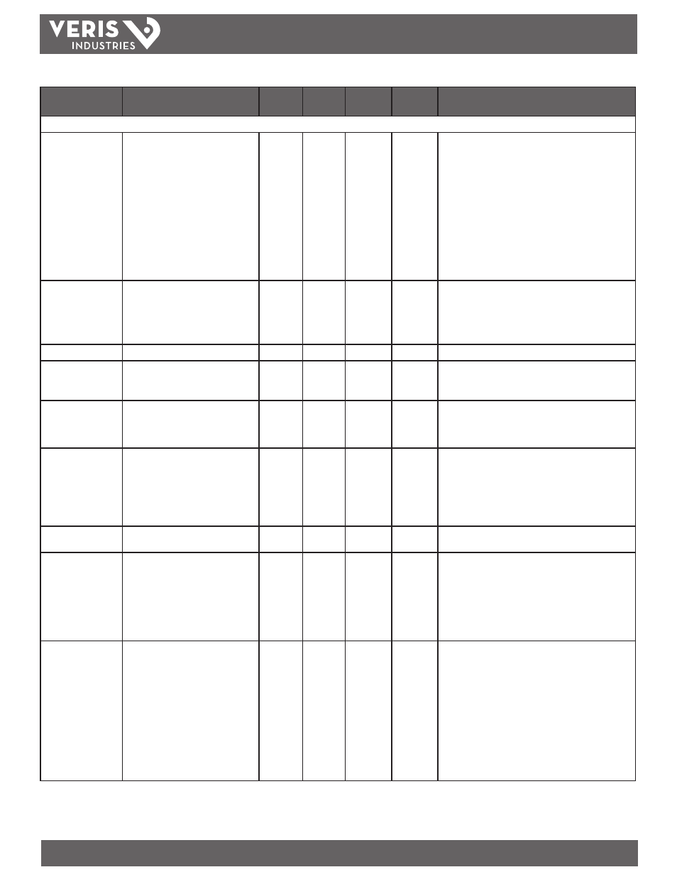
Data Variable
Description
BACnet
Object
Units
COV_
Increment
Modbus
Address
Comments
Analog_Value objects: (can be written as well as read)
Reset: write values to
reset configs
30078=Acc 21211=Dmd 21212=Max
16498=Puls
AV1
n/a
0
129
Reset (aka Command Register):
- Write 30078 (0x757E) to clear all Energy Accumulators to
0 (All).
- Write 21211 (0x52DB) to begin new Demand Sub-Interval
calculation cycle. Takes effect at the end of the next 1 second
calculation cycle. For proper operation, write no more
frequently than every 10 seconds.
- Write 21212 (0x52DC) to reset Max Demand values to
Present Demand Values. Takes effect at the end of the next
1 second calculation cycle. For proper operation, write no
more frequently than every 10 seconds.
- Write 16498 (0x4072) to clear Pulse Counts to zero.
- Read always returns 0.
System Type (being
metered)
10=1ph 11=2ph 12=2ph+N 31=3ph-Y
40=3ph+N
AV2
n/a
0
130
10 = Single Phase: A + N
11 = Single Phase: A + B
12 = Single Split Phase: A + B +
31 = 3 phase Δ, A + B + C, no N
40 = 3 phase Y, A + B + C + N
CT Ratio Primary CT Ratio Primary (5A to 32000A)
AV3
Amps
0
131
Current Transducer Size - Primary Current Range
CT Ratio Secondary CT Ratio Secondary (1=1VAC 3=1/3VAC)
AV4
n/a
0
132
Current Transducer Type – Secondary Interface
- Enter 1 for CTs with 1V outputs
- Enter 3 for CTs with 1/3V outputs
PT Ratio Potential Transformer Ratio (1= no PT)
AV5
n/a
0
133
PT Ratio: The meter scales this value by 100 (i.e. entering 200
yields a potential transformer ratio of 2:1). The default is 100
(1.00:1), which is with no PT attached. Set this value before
setting the system voltage (below)
System Voltage Line-Line Voltage of Service Metered
AV6
Volts
0
134
System Voltage: This voltage is line to line, unless in system
type 10 (AV2), which is line to neutral.
The meter uses this value to calculate the full scale power for
the pulse configuration (below), and as full scale for phase
loss (AV8). The meter will refuse voltages that are outside
the range of 82-660 volts when divided by the PT Ratio
(above).
Display Units Display Units (0=IEC 1=iEEE)
AV7
n/a
0
137
Display Units: 0 = IEC (U, V, P, Q, S), 1 = IEEE (default: VLL,
VLN, W, VAR, VA)
Phase Loss Voltage
Threshold
Phase Loss Thresh (% of System Voltage)
AV8
Percent
0
142
Phase Loss Voltage Threshold in percent of System Voltage (in
object AV6). Default is 10 (10%). Any phase (as configured in
AV2) whose level drops below this threshold triggers a Phase
Loss alert. E.g., if the System voltage is set to 480 V L-L,
the L-N voltage for each phase should be 277 V. When the
threshold is set to 10%, if any phase drops below 27.7, or if
any L-L voltage drops below 48 V, the corresponding phase
loss alarm bit will be true.
Phase Loss Imbalance
Threshold
Phase Loss Imbalance (% L-L variation)
AV9
Percent
0
143
Phase Loss Imbalance Threshold in Percent. Default is 25%
phase to phase difference. For a 3-phase Y (3 + N) system
type (40 in object AV2), both Line to Neutral and Line to Line
voltages are tested. In a 3-phase Δ System type (31 in object
AV2), only Line to Line voltages are examined. In a single
split-phase (2 + N) system type (12 in object AV2), just the
line to neutral voltage are compared. E.g., if the System Type
is 40 (3-phase with Neutral) and the Phase Loss Imbalance
Threshold is 25%, a Phase Imbalance is indicated when the
L-L voltage between any two phases drops to less than 75%
of the L-L voltage between any other two phases or when
the L-N voltage of any phase drops to less than 75% of the
L-N voltage of any other phase.
E51C2 and E51C3 Bi-Directional Energy Meter, cont.