Installation guide, E8950 – Veris Industries E8950 Install User Manual
Page 14
TM
E8950
INSTALLATION GUIDE
ZL0105-0B
PAGE 14
©2013 Veris Industries USA 800.354.8556 or +1.503.598.4564 / [email protected]
02131
Alta Labs, Enercept, Enspector, Hawkeye, Trustat, Aerospond, Veris, and the Veris ‘V’ logo are trademarks or registered trademarks of Veris Industries, L.L.C. in the USA and/or other countries.
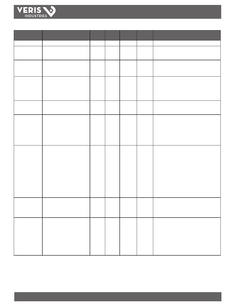
Data Variable
Description
BACnet
Object
Units
COV_
Increment
Modbus
Address
Comments
CT Ratio Primary CT Ratio Primary (5A to 32000A)
AV3
Amps
0
131
Current Transducer Size - Primary Current Range
CT Ratio Secondary CT Ratio Secondary (1=1VAC 3=1/3VAC)
AV4
n/a
0
132
Current Transducer Type – Secondary Interface
- Enter 1 for CTs with 1V outputs
- Enter 3 for CTs with 1/3V outputs
PT Ratio Potential Transformer Ratio (1 = no PT)
AV5
n/a
0
133
PT Ratio: The meter scales this value by 100 (i.e. entering 200
yields a potential transformer ratio of 2:1). The default is
100 (1.00:1), which is with no PT attached. Set this value
before setting the system voltage (below)
System Voltage Line-Line Voltage of Service Metered
AV6
Volts
0
134
System Voltage: This voltage is line to line, unless in system
type 10 (AV2), which is line to neutral.
The meter uses this value to calculate the full scale power
for the pulse configuration (below), and as full scale for
phase loss (AV8). The meter will refuse voltages outside the
range of 82-660 volts when divided by the PT Ratio (above).
Display Units Display Units (0=IEC 1=iEEE)
AV7
n/a
0
137
Display Units:
0 = IEC (U, V, P, Q, S)
1 = IEEE (default: VLL, VLN, W, VAR, VA)
Phase Loss Voltage
Threshold
Phase Loss Thresh (% of System Voltage)
AV8
Percent
0
142
Phase Loss Voltage Threshold in percent of System Voltage
(in object AV6). Default is 10 (10%). Any phase (as
configured in AV2) whose level drops below this threshold
triggers a Phase Loss alert. E.g., if the System voltage is set
to 480 V L-L, the nominal L-N voltage for each phase should
be 277 V. When the threshold is set to 10%, if any phase
drops below 27.7 V, or if any L-L voltage drops below 48 V
the corresponding phase loss alarm bit is true.
Phase Loss Imbalance
Threshold
Phase Loss Imbalance (% L-L variation)
AV9
Percent
0
143
Phase Loss Imbalance Threshold in Percent. Default is 25%
phase to phase difference. For a 3-phase Y (3 + N) system
type (40 in object AV2), both Line to Neutral and Line to
Line voltages are tested. In a 3-phase Δ System type (31 in
object AV2), only Line to Line voltages are examined. In a
single split-phase (2 + N) system type (12 in object AV2),
just the line to neutral voltage are compared. E.g., if the
System Type is 40 (3-phase with Neutral) and the Phase
Loss Imbalance Threshold is 25%, a Phase Imbalance is
indicated when the L-L voltage between any two phases
drops to less than 75% of the L-L voltage between any
other two phases or when the L-N voltage of any phase
drops to less than 75% of the L-N voltage of any other
phase.
Num of Sub-Intrvl per
Dem Intrvl
1=most recent; n(2-6)=avg of last n
AV10
n/a
0
149
Number of Sub-Intervals per Demand Interval. Sets the
number of sub-intervals that make a single demand
interval. For block demand, set this to 1. Default is 1. When
Sub-Interval Length (in object AV11) is set to 0 (sync-to-
comms mode), the value of this object is ignored.
Sub-Interval Length 10 to 32767 seconds (0= Sync-to-
Comms)
AV11
Seconds
0
150
Sub-Interval Length in hundredths of a second. For sync-to-
comms mode, which allows manual triggering of demand
intervals and the logging of another Trend_Log record, set
this value to 0 and write 21211 to the reset register (object
AV1) each time the sub-interval must be externally reset.
Default is 90000 (15 minutes). This variable is tied directly
to the Log_Interval property of all three Trend_Log objects
(their value is always the same as this one). Changing any
of these four properties
changes all of them.
E50C2 and E50C3 Uni-Directional Energy Meter, cont.