Omron Programmable Terminals NT31 NT31C User Manual
Page 99
5-1
Section
Connecting to the Host’s RS-232C Port
88
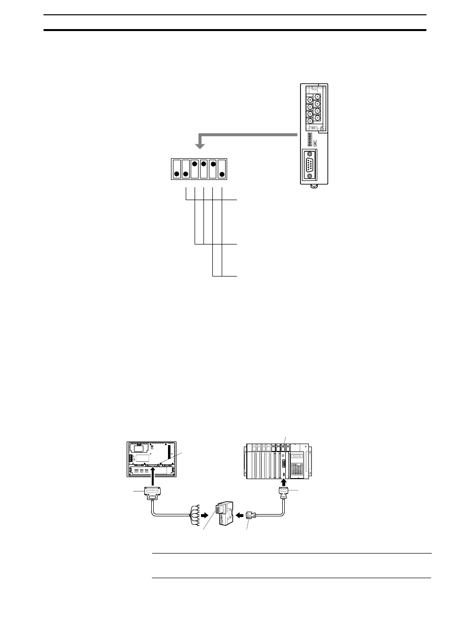
When making a connection between RS-232C and RS-422A/485 ports using an
RS-232C/RS-422A convertor unit, set the DIP switches on the NT-AL001 as fol-
lows.
1
2
3
4
5
6
ON
om on
R
NT-AL001
Built-in terminal resistor setting (DIP SW1-2)
If at the end of the RS-422A/485 cable, set this switch to ON (to
activate the built-in terminal resistor).
If not at the end of the RS-422A/485 cable, set this switch to
OFF (to inactivate the built-in terminal resistor).
2-wire type/4-wire type selection (DIP SW1-3, SW1-4)
For RS-422A, set both of these switches to OFF (4-wire type).
For RS-485, set both of these switches to ON (2-wire type).
Selection of RS-422A/485 send mode (DIP SW1-5, SW1-6)
For host link or NT link (1:1), set both of these switches to
OFF. (Always send)
For NT link (1:N), set SW1-5 to OFF and SW1-6 to ON.
(Sends when CS is H)
Example: the terminal resistor is active,
RS-422A, NT link (1:N).
Note Read the manual supplied with the NT-AL001 carefully before using the unit.
5-1-2 1:1 Connection between RS-422A/485 at the PT and RS-232C at
the Host
The connection method in which the RS-422A/485 port of an NT31/NT31C and
the RS-232C port of a host are connected via a convertor unit is described here.
An RS-232C/RS-422A convertor unit (NT-AL001) is used to convert between
the RS-232C and RS-422A communication methods.
NT31/NT31C
Serial port B
(RS-422A/485,
25-pin type)
Host link unit/CPU
SYSMAC
C-series PC,
CVM1/CV-series PC, SRM1
25-pin connector
RS-232C/RS-422A
convertor unit
(NT-AL001)
9-pin connector or
25-pin connector
RS-422A/485 cable
(max. length: 500 m)
RS-422A terminal block
9-pin connector
RS-232C cable
with connectors
Reference: When using RS-485 as a port for the NT31/NT31C, only NT link (1:N) method
(standard or high-speed) can be used.
Settings at the
RS-232C/RS-422A
Convertor Unit
(NT-AL001)