Pin arrangement, Rs-232c connector – Omron Programmable Terminals NT31 NT31C User Manual
Page 271
7
5
3
1
8
6
4
2
6
7
8
9
1
2
3
4
5
Appendix C
Using an RS-232C/RS-422A Convertor Unit
263
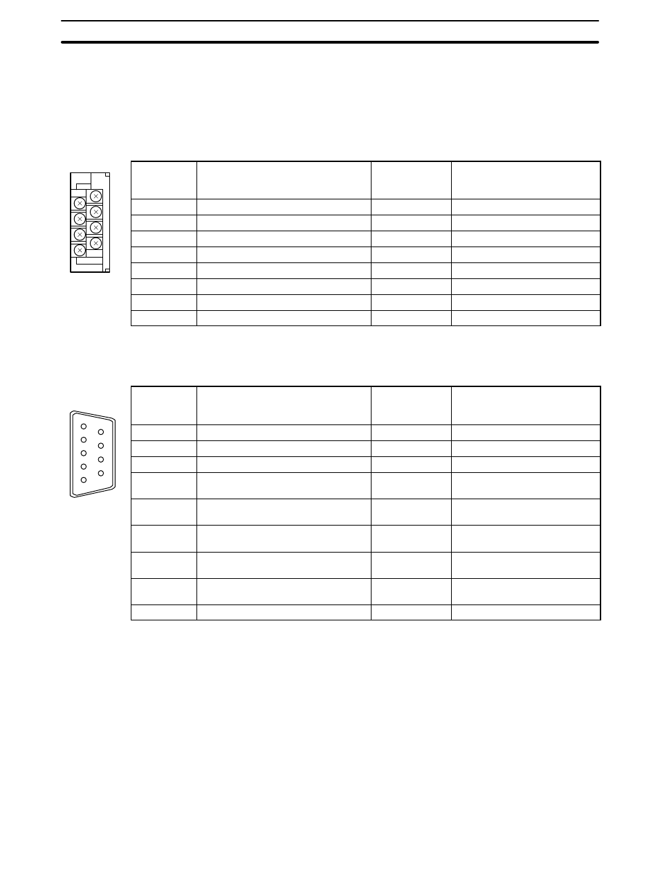
Pin Arrangement
The convertor unit has a terminal block for an RS-422A/485 interface connection and a connector for an RS-232C
interface connection.
The pin arrangements for the RS-422A/485 terminal block and the RS-232C connector are as follows.
RS-422A/485 Terminal Block
Terminal
block pin
No.
Signal name
Abbreviation
Signal direction
(convertor unit
⇔ RS-422
device)
8
Request to send (
−)
CSA
→
7
Request to send (+)
CSB
→
6
Receive data (
−)
RDA
←
5
Receive data (+)
RDB
←
4
Send data (
−)
SDA
→
3
Send data (+)
SDB
→
2
Signal ground
SG (GND)
–
1
Functional ground
–
* The CSB and CSA signals are for specialized applications.
RS-232C Connector
Connector
pin No.
Signal name
Abbreviation
Signal direction
(convertor unit
⇔ RS-232C
device)
1
Not used
–
–
2
Send data
SD
←
3
Receive data
RD
→
4
Request to send
(shorted to CS internally)
RS
←
5
Clear to send
(shorted to RS internally)
CS
→
6
+5 V (150 mA) input for convertor
unit
+5 V
→
7
Data set ready
(shorted to ER internally)
DR
→
8
Data terminal ready
(shorted to DR internally)
ER
←
9
Signal ground
SG
–
* The hood is connected to the functional ground terminal of the RS-422A terminal block.