Block diagram – Omron Programmable Terminals NT31 NT31C User Manual
Page 272
Appendix C
Using an RS-232C/RS-422A Convertor Unit
264
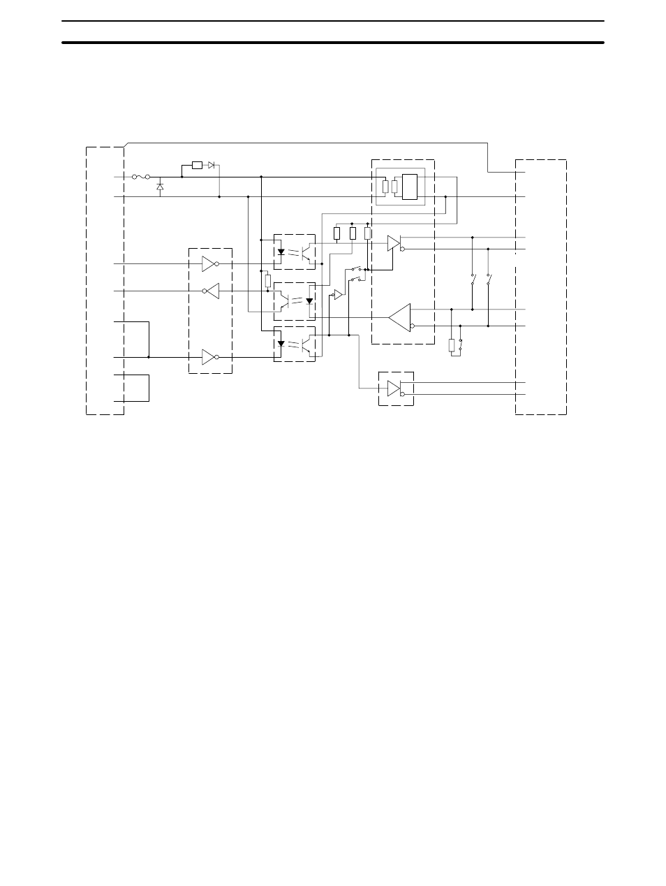
Block Diagram
A diagram showing the internal blocks of the convertor unit is shown below. Refer to this diagram when making
cables yourself, or when connecting devices with special interfaces.
SW1-6
Terminator
R
R
D-SUB 9P CASE
+5 V
SG
SD
RD
RS
CS
DR
ER
6
9
2
3
4
5
7
8
POWER
LED
RS-232C
Dr/Rec
RS-422A/485 Dr/Rec
DC-DC
IS_5 V
IS_0 V
FG
1
2
3
4
6
5
7
8
SW1-5
SW1-4
SG
SDB
SDA
RDB
RDA
CSB
CSA
SW1-2
RS-422A Dr
SW1-3
RS-232C side
Fuse
Convertor
RS-422A/485 side
8P terminal block
Photocoupler
2-wire type/
4-wire type
R
R
R
R
L
L
REG