Connecting between nt31/nt31c units – Omron Programmable Terminals NT31 NT31C User Manual
Page 137
5-2
Section
Connecting to the Host’s RS-422A/485 Port
126
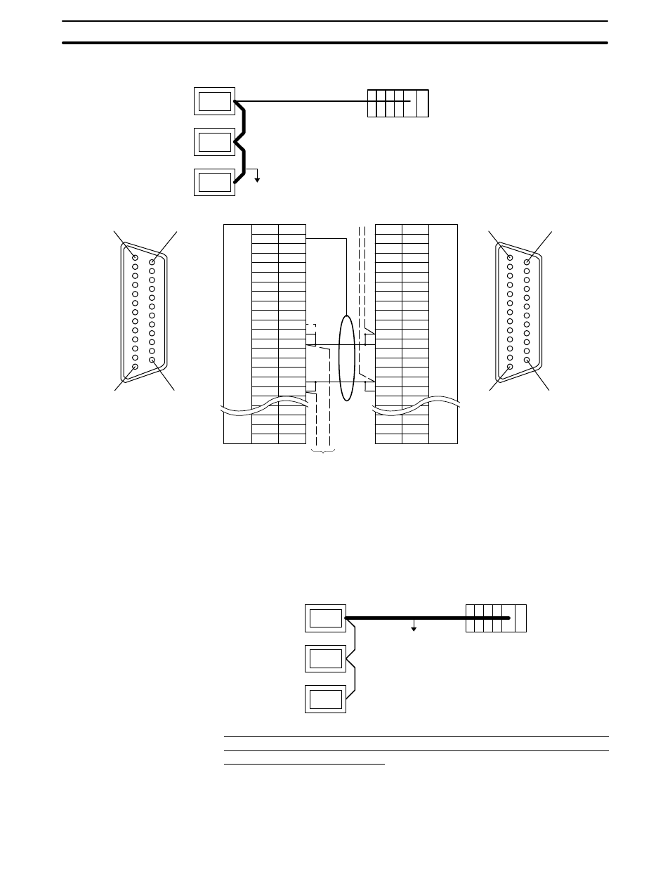
Connecting between NT31/NT31C Units
:
Next PT
Shielding wire
:
RS-485
Host
NT31/NT31C side
(25-pin type)
Abbreviation
FG
−
SD
RD
RS
CS
−
SG
−
TRM
RDB (+)
SDB (+)
−
−
−
SDA (
−)
RDA (
−)
−
−
RSB (+)
RSA (
−)
−
Pin number
Connector
hood
1
2
3
4
5
6
7
8
9
10
11
12
13
14
15
16
−
23
24
25
RS-232C/
422A/485
connector
RS-232C/
422A/485
connector
Abbreviation
FG
−
SD
RD
RS
CS
−
SG
−
TRM
RDB (+)
SDB (+)
−
−
−
SDA (
−)
RDA (
−)
−
−
RSB (+)
RSA (
−)
−
Pin number
Connector
hood
1
2
3
4
5
6
7
8
9
10
11
12
13
14
15
16
−
23
24
25
(25-pin type)
NT31/NT31C side
1
14
13
25
1
14
13
25
NT31/NT31C
*2
Make the connection between pin numbers 9 and 10 at the NT31/NT31C at the
end of the RS-485 cable (marked
:
in the figure above) only.
In order to avoid an FG ground loop, do not connect the functional ground of the
NT31/NT31C to the shielding of the RS-422A cable.
The relay terminal block is not included in this figure. Insert the relay terminal
block so as to achieve the wiring configuration shown below.
RS-485
NT31/NT31C
Host
Wiring When Connecting a CS1-series CS1G/H Serial Communication
Board, C Series C200HX/HG/HE(-Z)E Communication Board, or CQM1H
Serial Communications Board
Applicable units:
CS1G-CPU42-E(V1)
CS1G-CPU43-E(V1)
CS1G-CPU44-E(V1)
CS1G-CPU45-E(V1)
CS1H-CPU63-E(V1)
CS1H-CPU64-E(V1)
Connecting an
NT31/NT31C and a Host