1 installation, 1-1 installation environment, 1-2 installation in the operation panel – Omron Programmable Terminals NT31 NT31C User Manual
Page 43
3-1
Section
Installation
32
Note On unpacking the NT31/NT31C and peripheral devices, check their external ap-
pearance and confirm that there is no damage. Also confirm that there is no ab-
normal noise on shaking the unit lightly.
3-1
Installation
Install the NT31/NT31C in the operation panel and connect the power to the
NT31/NT31C as described below.
3-1-1 Installation Environment
Observe the following points when installing the PT in an operation panel.
Note
1. Do not install the unit at sites subject to the following conditions.
• Severe temperature variations
• Temperatures or humidities outside the ranges stated in the specifications
• High humidity, condensation
• Splashing chemical agents
• Severe oil splashing
• Corrosive or flammable gases
• Strong vibrations or shocks
• Direct exposure to wind and rain (outdoor sites)
• Strong ultra-violet irradiation
2. Take adequate measures to ensure shielding if the unit is used at a location
subject to any of the following conditions.
• Static electricity, or noise from other equipment
• Strong electromagnetic fields
• Nearby power cables
• Potential exposure to radioactivity
3-1-2 Installation in the Operation Panel
The NT31/NT31C is mounted in an operation panel by embedding it in the panel.
Use the panel fittings and tool (Philips screwdriver) included in the product pack-
age and follow the procedure below.
1, 2, 3...
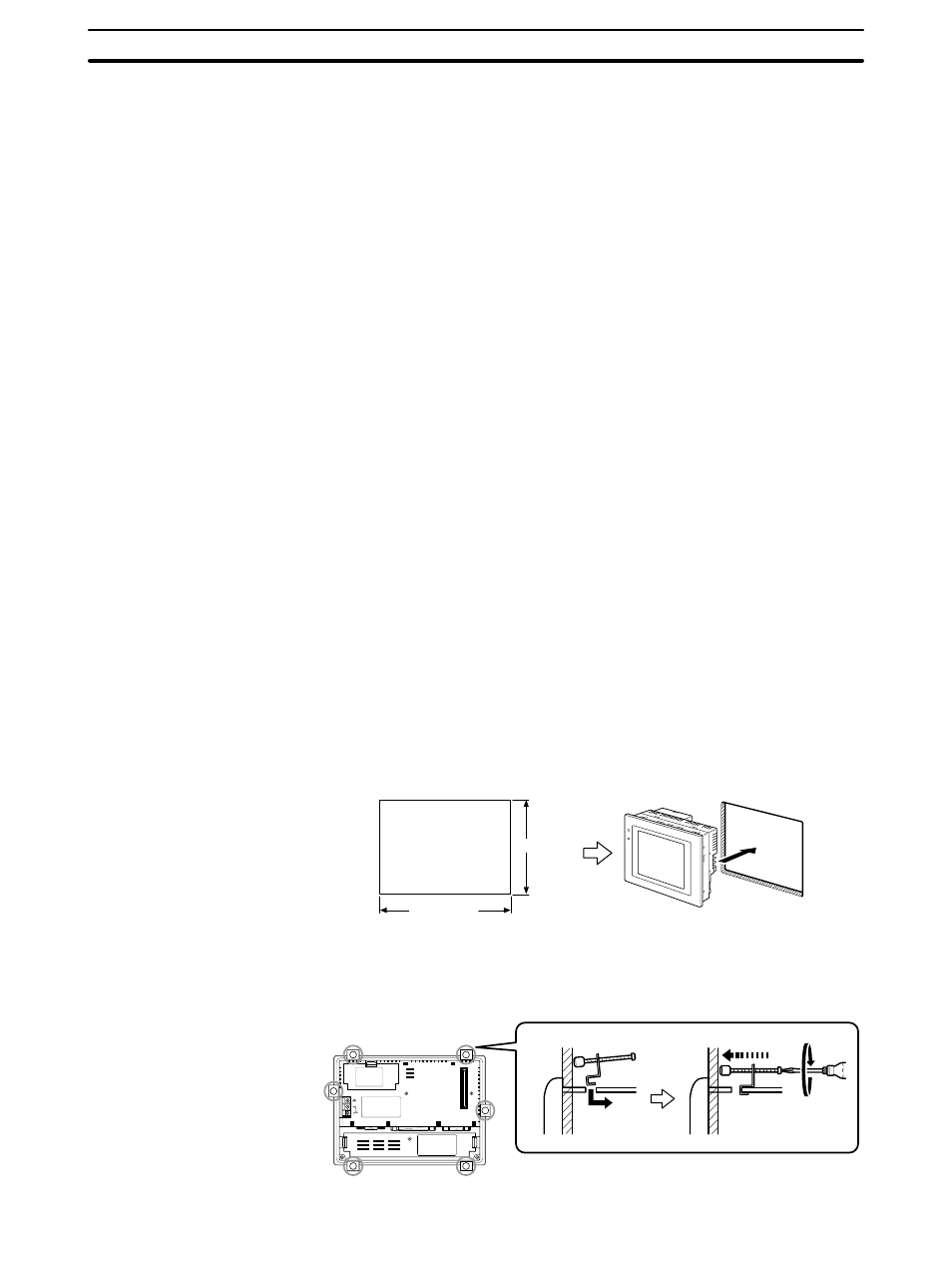
1. Open a hole of the dimensions shown below in the panel and install the
NT31/NT31C from the front side of the panel.
131
+ 0.5 mm
0
mm
184
+ 0.5 mm
0
mm
2. Attach the panel fittings at the four positions at top and bottom and two posi-
tions at right and left, shown below, from the rear of the NT31/NT31C.
Fit the hook of the fitting in the square hole in the body and tighten the screw
with the Philips head screwdriver while lightly pulling the fitting.
24V
DC
PRINTER
PORT B
PORT A