Omron Programmable Terminals NT31 NT31C User Manual
Page 72
4-1
Section
Connecting to the RS-232C Port at the Host
61
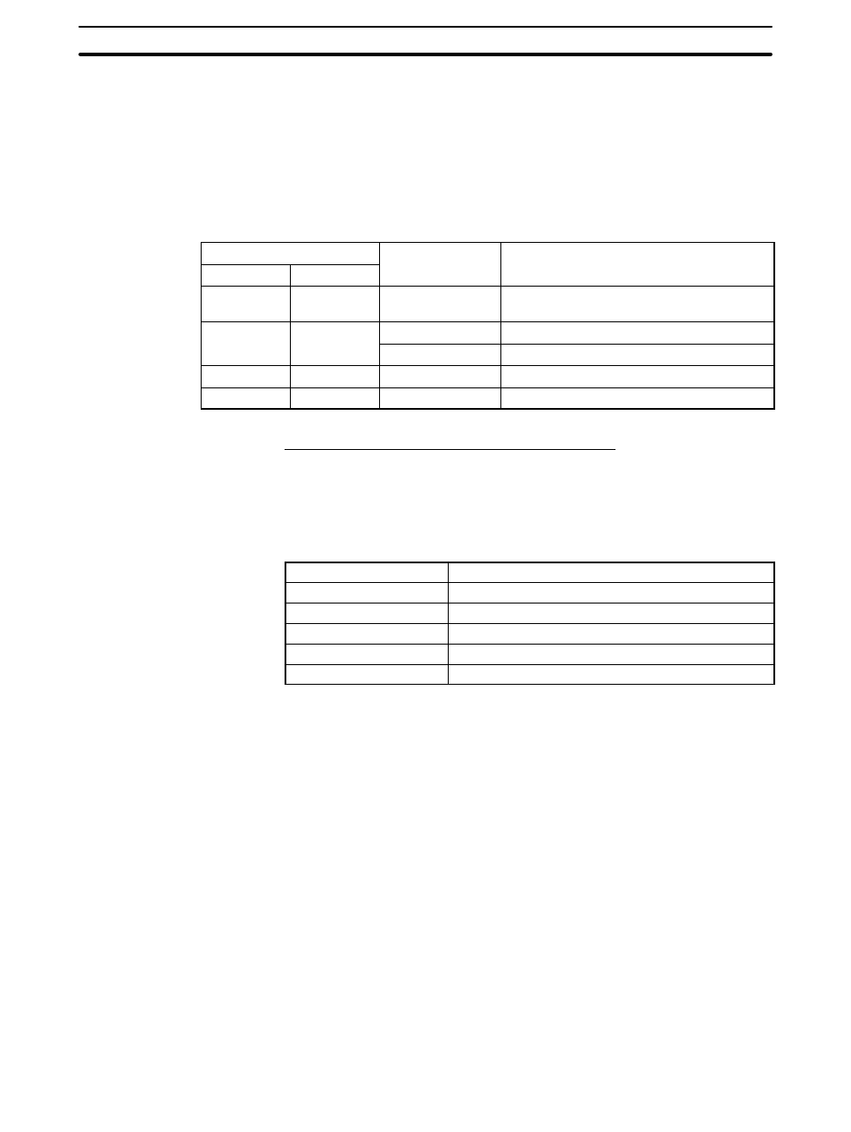
Allocation DM Area Settings for CPU
Settings are written from the Programming Device (a Programming Console or
CX-Programmer) directly into the allocation DM area (system setting area) of
the CPU. After the settings are written, they become effective by turning the
power ON, restarting the unit, restarting the communication port, or execution of
the STUP command.
In the following, the channel numbers of the allocation DM area and the settings
are shown.
m=DM30000+100
×unit # (CH)
Allocation DM area (CH)
Writing Value
Settings
Port 1
Port 2
Writing Value
Settings
m
m+10
8000
host link mode, 2 stop bits, even parity, data
length 7 bits
m+1
m+11
0000
Communication speed 9600 bps.
m+1
m+11
0007
Communication speed 19200 bps.
m+2
m+12
0000
Transmit delay time 0 ms.
m+6
m+16
0000
No CTS control Unit No.0 for host link
Connecting to a CPU Unit
CV-series and CVM1/CV-series (-EV
j) CPU Units
• CV500-CPU01-EV1/CV1000-CPU01-EV1/CV2000-CPU01-EV1
• CVM1-CPU01-EV2/CVM1-CPU11-EV2/CVM1-CPU21-EV2
PC Setup
When connecting to a CVM1/CV series CPU, set the following communication
conditions for the PC Setup.
Item
Setting at Host
Communications speed
Set the same speed as set at the NT31/NT31C
(*1)
Stop bit
2 stop bits
Parity
Even
Data length
ASCII 7 bits
Unit #
00
*1 Set the host link communications speed at 9600 bps or 19200 bps with the
memory switch at the NT31/NT31C. For details, refer to Setting the Host Link
Method (page 160).
Either set PC Setup directly from a Programming Device (e.g. SYSMAC support
software), or transmit the PC Setup made at a Programming Device to the CPU.
For details on the PC Setup, refer to the SYSMAC CVM1/CV500/1000/2000 Op-
eration Manual: Ladder Diagrams (W202-E1-
j).