Made by jae – Omron Programmable Terminals NT31 NT31C User Manual
Page 139
5-2
Section
Connecting to the Host’s RS-422A/485 Port
128
Name
Remarks
Maker
Model
Connector
XM2S-2511
25-pin type
Made by OMRON
Delivered with the following
units:
C500-LK203
Connector
hood
DB-C2-J9
25-pin type
Made by JAE
Delivered with the following
units:
3G2A6-LK201-EV1
3G2A5-LK201-EV1
Cable
TKVVBS4P-03
Tachii Electric
Wire Co., Ltd.
Crimp
1.25-N3A
(fork type)
Japan Solderless
Terminal MFG
Recommended cable size:
AWG22 t 18
Crimp
terminals
Y1.25-3.5L
(fork type)
Molex Inc.
AWG22 to 18
(0.3 to 0.75 mm
2
)
The terminal screws of the RS-422A adaptor (CPM1-CIF11) are M3 specifica-
tion. When wiring, use crimp terminals for M3 use. Tighten terminal screws with
a tightening torque of 0.5 N
@m.
Use the same specification of the terminal screws which is used in the relay ter-
minal block.
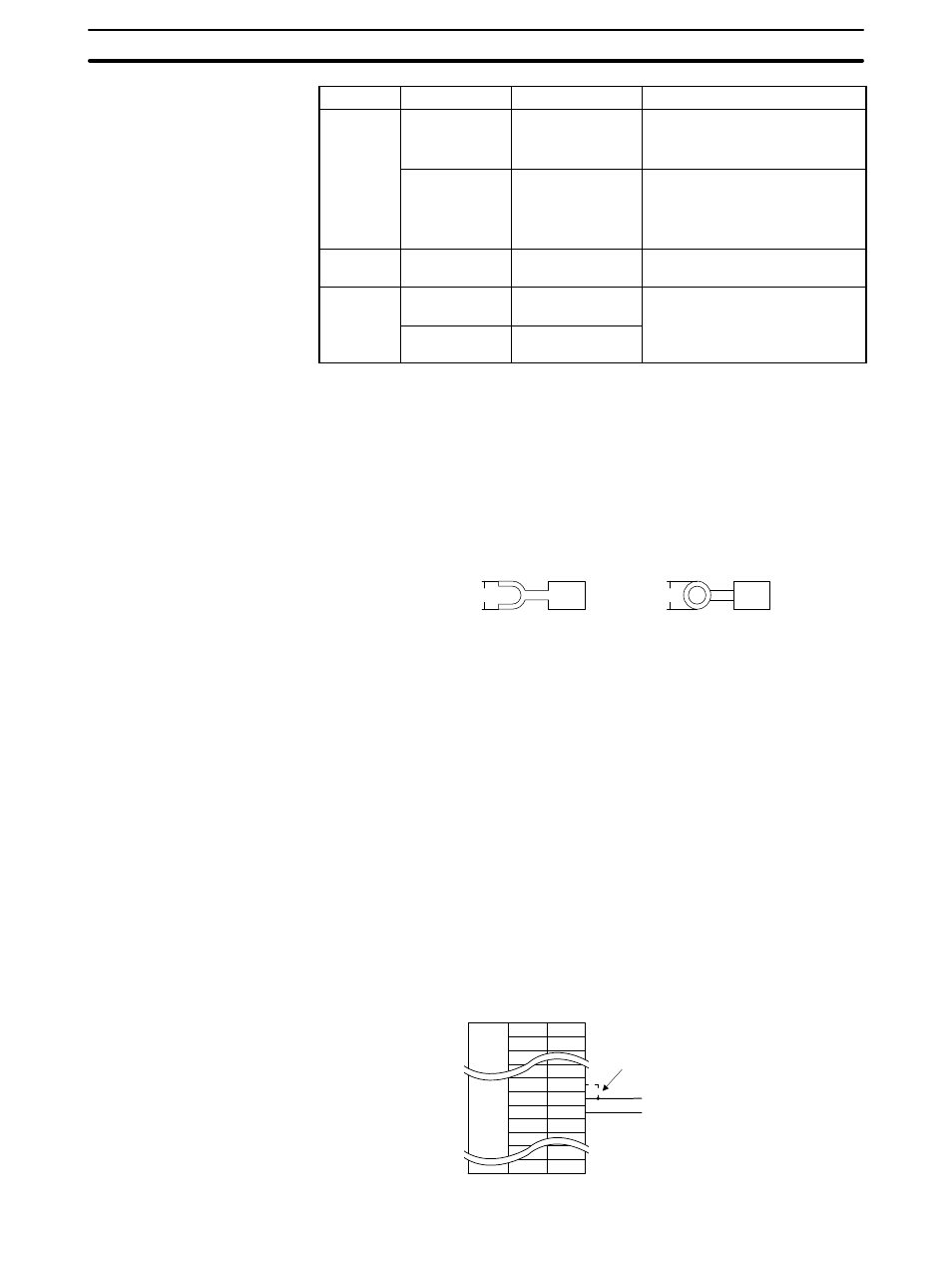
Note Always use crimp terminals for wiring.
Examples of applicable terminals
Fork type
6.2 mm or less
Round type
6.2 mm or less
5-2-7 Setting the Terminal Resistance for RS-422A/485 Communications
The serial port B connector of the NT31/NT31C has a terminal resistance setting
terminal (TRM).
In RS-422A/485 communications, a terminal resistor must be set at the device at
the end of the communication cable, but not at any other device.
The NT31/NT31C has a built-in terminal resistor, and whether or not the terminal
resistance is applied is set by the wiring at the terminal resistance setting termi-
nals (pins No. 9 and 10 of serial port B). The terminal resistance is 120
Ω. When
carrying out RS-422A/485 communications using serial port B, short between
terminals No. 9 and 10 at the NT31/NT31C at the end of the RS-422A/485 cable.
Leave terminals No. 9 and 10 open at NT31/NT31C units other than the one at
the end of the cable.
When not using RS-422A/485 communications, the terminal resistance setting
is ineffective.
In order to set the terminal resistance, wiring work is required at the cable’s con-
nector: carry out the wiring correctly by referring to APPENDIX E Making the
Cable, page 267.
Abbreviation
FG
-
-
TRM
RDB (+)
SDB (+)
-
-
-
Pin number
Connector
hood
-
9
10
11
12
-
25
Terminal resistor setting