Omron Programmable Terminals NT31 NT31C User Manual
Page 103
5-1
Section
Connecting to the Host’s RS-232C Port
92
If there is +5 V output at the PC side, no external power supply is required for
the NT-AL001.
Wiring for a Memory Link Connection
Prepare the adapter cable while referring to the diagram shown below.
(9-pin type)
Shielding wire
No +5 V output is at the host side
A +5 V output is present at the host side
NT-AL001 side
Host side
1
6
5
9
Abbreviation
FG
−
SD
RD
RS
CS
+5V
−
−
SG
Pin number
Connector
hood
1
2
3
4
5
6
7
8
9
RS-232C
connector
RS-232C
connector
Abbreviation
Connector
hood
SD
RD
RS
CS
(+5V)
SG
Since it is necessary to input a voltage of +5 V to the number 6 pin of NT-AL001,
supplying a voltage of 5 V from the host or an external voltage supply for NT-
AL001 is required.
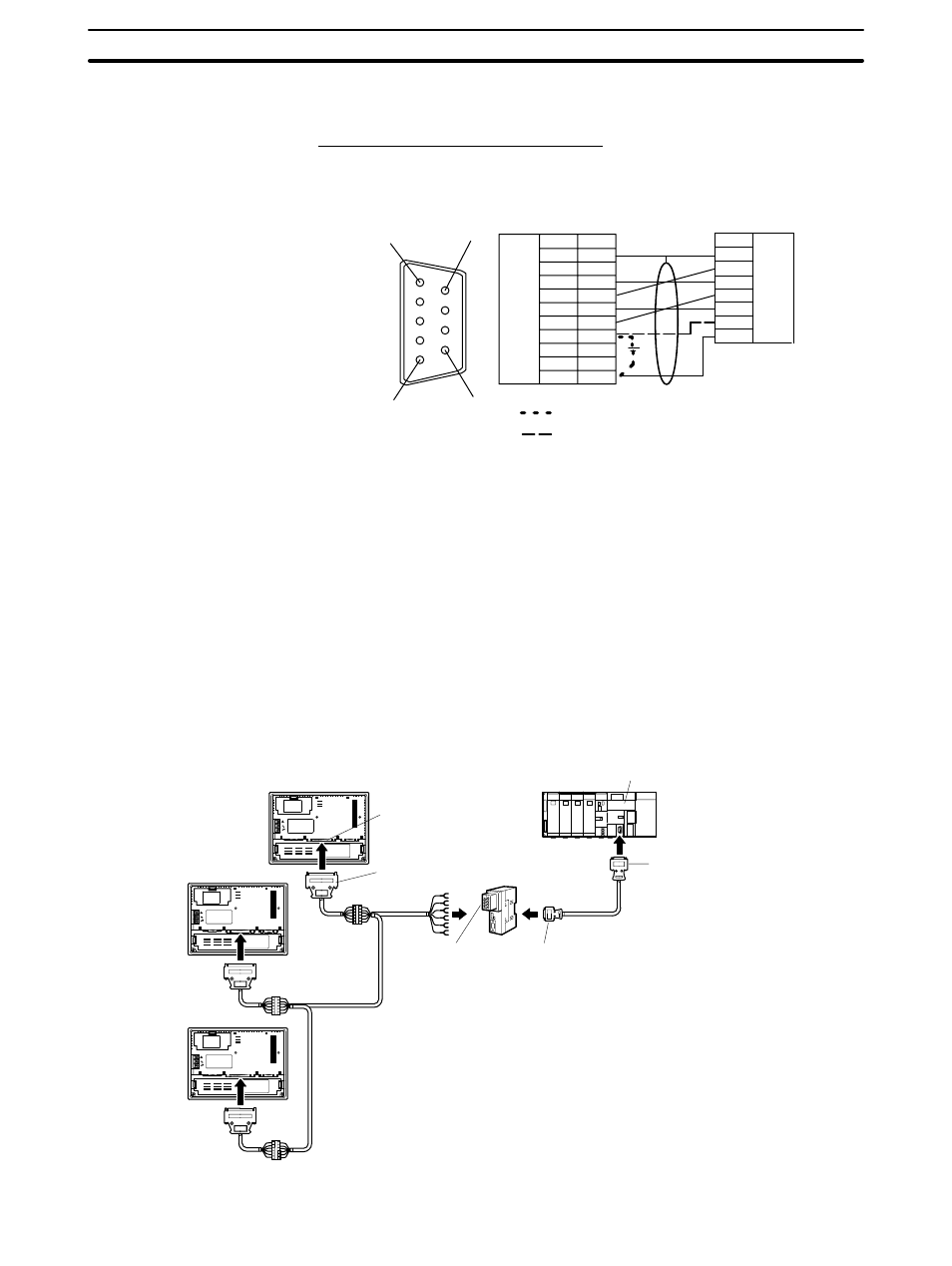
5-1-3 1:N Connection between RS-422A/485 at the PT and RS-232C at
the Host
The connection method in which the RS-422A/485 ports of multiple
NT31/NT31Cs are connected to the RS-232C port of one host in a 1:N connec-
tion is described here.
An RS-232C/RS-422A convertor unit (NT-AL001) is used to convert between
the RS-232C and RS-422A/485 communication methods.
NT31/NT31C
Serial port B
(RS-422A/485,
25-pin type)
Host link unit/CPU
CS1G/H
C200HX/HG/HE(-Z)E
25-pin connector
RS-232C/RS-422A
convertor unit
(NT-AL001)
9-pin connector
RS-422A/485 cable
(max. total length: 500 m)
RS-422A terminal
block
9-pin connector
RS-232C cable with
connectors
Max. 2 m
Relay terminal block