Omron Programmable Terminals NT31 NT31C User Manual
Page 131
5-2
Section
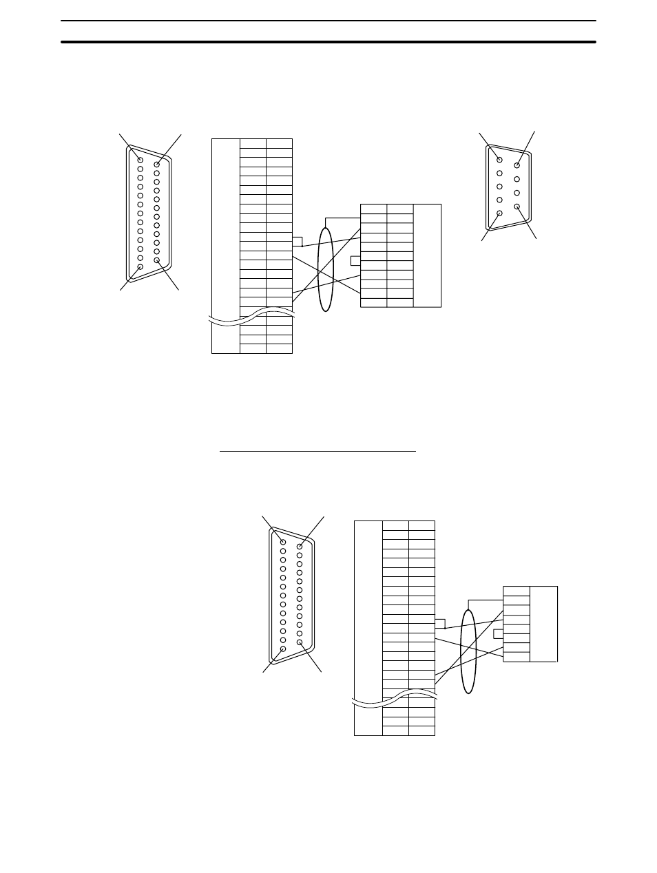
Connecting to the Host’s RS-422A/485 Port
120
CVM1/CV-series CPUs whose model names do not have the suffix -EV
j can-
not be connected by any connection method.
1
14
13
25
NT31/NT31C side
Shielding wire
(25-pin type)
Abbreviation
FG
−
SD
RD
RS
CS
−
SG
−
TRM
RDB (+)
SDB (+)
−
−
−
SDA (
−)
RDA (
−)
−
−
RSB (+)
RSA (
−)
−
Pin number
Connector
hood
1
2
3
4
5
6
7
8
9
10
11
12
13
14
15
16
−
23
24
25
RS-232C/
422A/485
connector
6
5
9
1
PC (CPU) side
RS-422A
connector
Pin number
Connector
hood
1
2
3
4
5
6
7
8
9
Abbreviation
FG
SDA
SDB
−
RS
CS
RDA
−
RDB
−
(9-pin type)
In order to avoid an FG ground loop, do not connect the functional ground of the
NT31/NT31C to the shielding of the RS-422A cable.
Wiring for a Memory Link Connection
Prepare the adapter cable while referring to the following diagram.
1
14
13
25
NT31/NT31C side
Shielding wire
(25-pin type)
Abbreviation
FG
−
SD
RD
RS
CS
−
SG
−
TRM
RDB (+)
SDB (+)
−
−
−
SDA (
−)
RDA (
−)
−
−
RSB (+)
RSA (
−)
−
Pin number
Connector
hood
1
2
3
4
5
6
7
8
9
10
11
12
13
14
15
16
−
23
24
25
RS-232C/
422A/485
connector
Host side
RS-422A
connector
Abbreviation
Connector
hood
SDA
SDB
RS
CS
ROA
ROB
In order to avoid an FG ground loop, do not connect the functional ground of the
NT31/NT31C to the shielding of the RS-422A cable.