Omron Programmable Terminals NT31 NT31C User Manual
Page 85
4-1
Section
Connecting to the RS-232C Port at the Host
74
*1 Set any value between 0000 and 0009 Hex for the communications baud rate.
The same baud rate will be used regardless of the value as long as it is between
0000 and 0009 Hex.
When connecting PT with its model number 0, 2-5 to the built-in RS-232C port,
for example, set the value 8200 Hex to 160 CH, and 0005 Hex to 166CH.
Either set PC Setup directly from a Programming Device (Programming Con-
sole), or transmit the PC Setup made at a Programming Device (CX-Program-
mer) to the CPU.
For details on PC Setup, refer to the SYSMAC CS1-series Operation Manual
(W339-E1
-
j
).
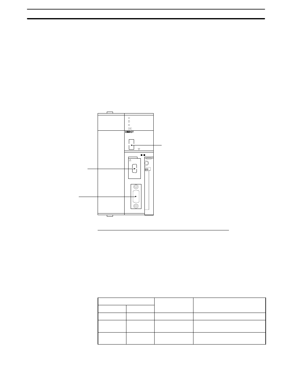
Setting the Front Switches
Set the CPU DIP switch to 4 or 5 in accordance with the port NT31/NT31C is
connected to.
Peripheral port
This is used mainly for
connection to the
Programming Device.
(This also supports the
RS-232C unit connection.)
RS-232 port
This is used mainly for
connection to the
RS-232C unit.
(This also supports the
CX-Programmer.)
DIP switches (inside the battery storage)
• Set SW4 to ON (establishing communication in ac-
cordance with PC Setup) when connecting the
NT31/NT31C to the peripheral port.
• Set SW5 to OFF (establishing communication in ac-
cordance with PC Setup) when connecting the
NT31/NT31C to the RS-232C port.
SYSMAC CS1G
PROGRAMMABLE CONTROLLER
CPU4
2
OPEN
OPEN
PERIPHERAL
PORT
BUSY
RUN
ERR/ALM
INH
PRPHL/COMM
MCPWR
Connecting to CS1 Series Serial Communications Board
Serial Communications Board equipped with a RS-232C port for CS1-series
CPU Units: CS1W-SCB41/21
CPU Allocation DM Area Settings
Setting is written from the Programming Device (a Programming Console or CX-
Programmer) directly into the allocation DM area (system setting area) of the
CPU. After the setting is written, it becomes effective by turning the power ON,
restarting the unit, restarting the communication port, or execution of the STUP
command.
In the following, the channel numbers of the allocation DM area and settings are
shown.
Allocation DM area (CH)
Writing Value
Settings
Port 1
Port 2
Writing Value
Settings
DM32000
DM32010
8200
NT link (1:N) mode
DM32001
DM32011
0000 to 0009
(*1)
Communications baud rate
(standard)
DM32006
DM32016
000
j
j = The largest model number of
the connected PT (0 – 7)
*1 Set any value between 0000 and 0009 Hex for the communications baud rate.
The same baud rate will be used regardless of the value as long as it is between
0000 and 0009 Hex.