Omron Programmable Terminals NT31 NT31C User Manual
Page 91
4-1
Section
Connecting to the RS-232C Port at the Host
80
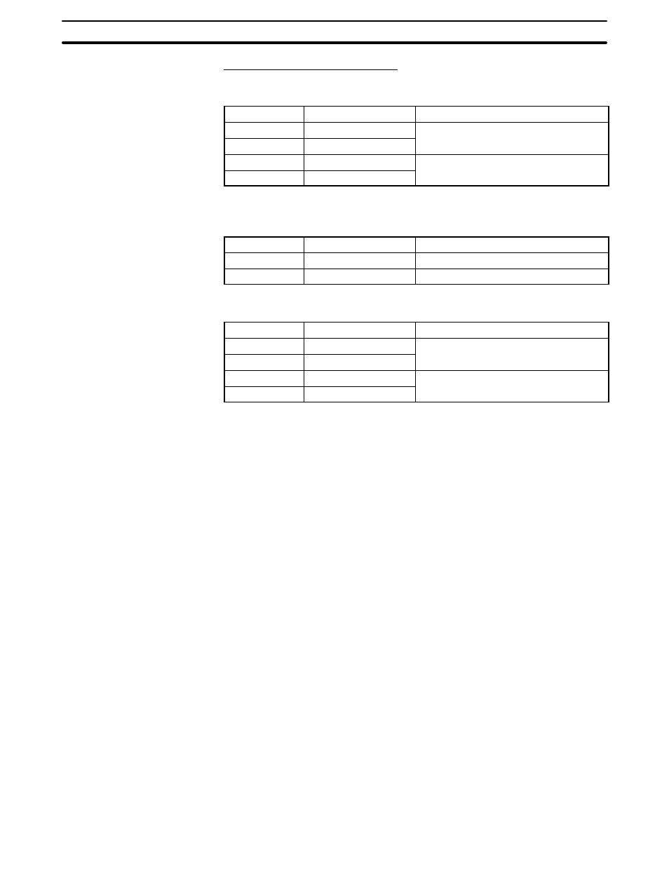
OMRON Cables with Connectors
When a connection is made at serial port A in other than the memory link meth-
od, OMRON cables with connectors shown below are available.
Model
Cable Length
Connector Specification
XW2Z-200S
2 m
9 pin
⇔ 25 pin
XW2Z-500S
5 m
9-pin
⇔ 25 pin
XW2Z-200T
2 m
9 pin
⇔ 9 pin
XW2Z-500T
5 m
9-pin
⇔ 9-pin
When a connection is made to a personal computer at serial port A in the
memory link method, OMRON cable with connectors shown below are avail-
able.
Model
Cable Length
Connector Specification
CV500-CN228
2 m
9-pin
⇔ 25 pin
XW2Z-S002
2 m
9-pin
⇔ 9 pin
When a connection is made at serial port B in other than the memory link meth-
od, OMRON cables with connectors shown are available.
Model
Cable Length
Connector Specification
XW2Z-200P
2 m
25 pin
⇔ 25 pin
XW2Z-500P
5 m
25-pin
⇔ 25 pin
XW2Z-200S
2 m
25 pin
⇔ 9 pin
XW2Z-500S
5 m
25-pin
⇔ 9-pin
Note The cable’s tensile load is 30 N. Do not subject it to loads greater than this.
Applicable units: C200H-LK201-EV1
3G2A5-LK201-EV1
C500-LK203
3G2A6-LK201-EV1
CV500-LK201 (communication port 1)
Cables with connectors that can be used at serial port A:
XW2Z-200S (9-pin
⇔
25-pin, 2 m)
XW2Z-500S (9-pin
⇔
25-pin, 5 m)
Cables with connectors that can be used at serial port B:
XW2Z-200P (25-pin
⇔
25-pin, 2 m)
XW2Z-500P (25-pin
⇔
25-pin, 5 m)
CVM1/CV-series host link units (CV500-LK201) have two types of connector; a
25-pin connector (communication port 1), and a 9-pin connector (communica-
tion port 2). When using communication port 2, refer to Wiring for Other Connec-
tions (Other Than the Memory Link Method) (page81).
Wiring for a Host Link
Unit (25-pin) Connection