External interrupts, Hardware, Function block operations – Renesas 4514 User Manual
Page 39
1-26
HARDWARE
4513/4514 Group User’s Manual
FUNCTION BLOCK OPERATIONS
Table 7 External interrupt activated conditions
Name
External 0 interrupt
External 1 interrupt
Input pin
P3
0
/INT0
P3
1
/INT1
Activated condition
When the next waveform is input to P3
0
/INT0 pin
• Falling waveform (“H”
→
“L”)
• Rising waveform (“L”
→
“H”)
• Both rising and falling waveforms
When the next waveform is input to P3
1
/INT1 pin
• Falling waveform (“H”
→
“L”)
• Rising waveform (“L”
→
“H”)
• Both rising and falling waveforms
Valid wavefor m
selection bit
I1
1
I1
2
I2
1
I2
2
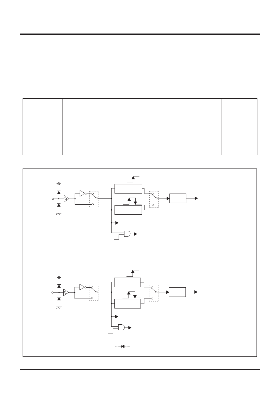
Fig. 17 External interrupt circuit structure
EXTERNAL INTERRUPTS
The 4513/4514 Group has two external interrupts (external 0 and
external 1). An external interrupt request occurs when a valid
waveform is input to an interrupt input pin (edge detection).
The external interrupts can be controlled with the interrupt control
registers I1 and I2.
0
1
I2
2
0
1
EXF1
I2
1
SNZI1
P3
1
/INT1
0
1
I1
2
Wakeup
Skip
0
1
EXF0
I1
1
SNZI0
P3
0
/INT0
Rising
Falling
One-sided edge
detection circuit
Both edges
detection circuit
External 0
interrupt
External 1
interrupt
Wakeup
Skip
Rising
Falling
One-sided edge
detection circuit
Both edges
detection circuit
This symbol represents a parasitic diode on the port.