2 oscillation operation, 3 notes on use, Application – Renesas 4514 User Manual
Page 167: 10 oscillation circuit
APPLICATION
2-64
4513/4514 Group User’s Manual
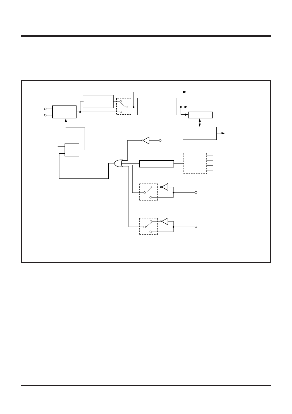
2.10 Oscillation circuit
2.10.2 Oscillation operation
System clock is supplied to CPU and peripheral device as the standard clock for the microcomputer
operation. For the 4513/4514 Group, the clock (f(X
IN
)), (f(X
IN
)/2) which is supplied from the oscillation
circuit is selected with the register MR.
Figure 2.10.2 shows the structure of the clock control circuit.
Fig. 2.10.2 Structure of clock control circuit
2.10.3 Notes on use
(1)
Value of a part connected to an oscillator
Values of a capacitor and a resistor of the oscillation circuit depend on the connected oscillator and
the board. Accordingly, consult the oscillator manufacturer for values of each part connected the
oscillator.
Instruction clock
MR
3
1
0
RESET
Falling detected
Ports P0
0
, P0
1
Ports P0
2
, P0
3
Ports P1
0
, P1
1
Ports P1
2
, P1
3
Multi-
plexer
K0
0
,K0
1
,K0
2
,K0
3
Counter
Wait time (Note)
control circuit
Software
start signal
R
S
Q
POF instruction
X
IN
X
OUT
I1
2
0
1
P3
0
/INT0
Key-on wake up control register
I2
2
0
1
P3
1
/INT1
Oscillation
circuit
Division circuit
(divided by 2)
Internal clock
generation circuit
(divided by 3)
“H” level
“L” level
“H” level
Note: The wait time control circuit is used to generate the time required to stabilize the f(X
IN
) oscillation.
System clock