Performance overview, Hardware – Renesas 4514 User Manual
Page 21
1-8
HARDWARE
4513/4514 Group User’s Manual
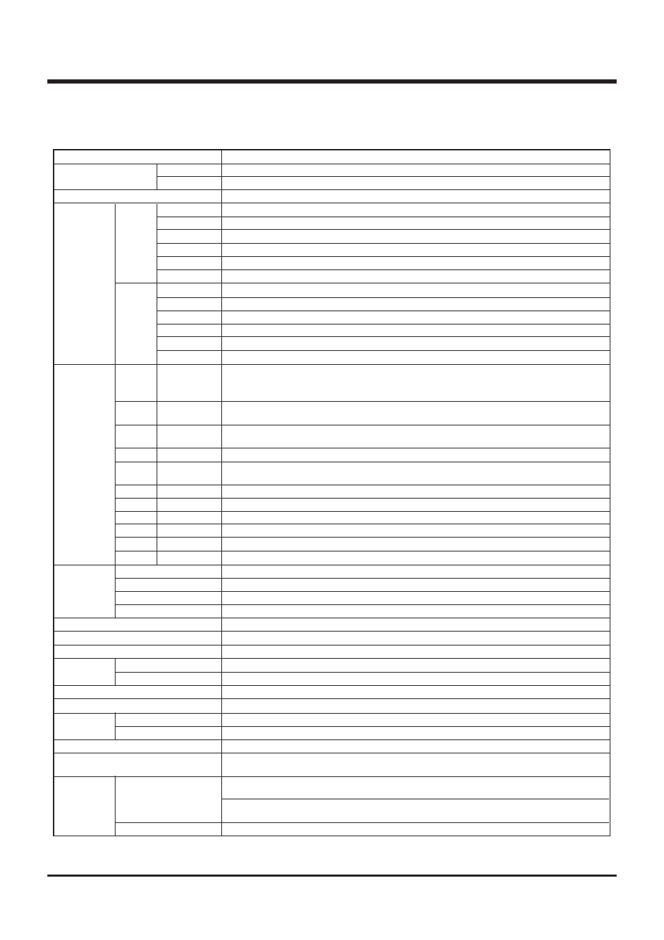
PERFORMANCE OVERVIEW
Function
123
128
0.75
µ
s (at 4.0 MHz oscillation frequency, in high-speed mode)
2048 words
✕
10 bits
4096 words
✕
10 bits
6144 words
✕
10 bits
8192 words
✕
10 bits
6144 words
✕
10 bits
8192 words
✕
10 bits
128 words
✕
4 bits
256 words
✕
4 bits
384 words
✕
4 bits
384 words
✕
4 bits
384 words
✕
4 bits
384 words
✕
4 bits
Eight independent I/O ports;
ports D
6
and D
7
are also used as CNTR0 and CNTR1, respectively.
4-bit I/O port; each pin is equipped with a pull-up function and a key-on wakeup function. Both
functions can be switched by software.
4-bit I/O port; each pin is equipped with a pull-up function and a key-on wakeup function. Both
functions can be switched by software.
3-bit input port; ports P2
0
, P2
1
and P2
2
are also used as S
CK
, S
OUT
and S
IN
, respectively.
4-bit I/O port (2-bit I/O port for the 4513 Group); ports P3
0
and P3
1
are also used as INT0 and
INT1, respectively. The 4513 Group does not have ports P3
2
, P3
3
.
4-bit I/O port; The 4513 Group does not have this port.
4-bit I/O port with a direction register; The 4513 Group does not have this port.
1-bit I/O; CNTR0 pin is also used as port D
6
.
1-bit I/O; CNTR1 pin is also used as port D
7
.
1-bit input; INT0 pin is also used as port P3
0
and equipped with a key-on wakeup function.
1-bit input; INT1 pin is also used as port P3
1
and equipped with a key-on wakeup function.
8-bit programmable timer with a reload register.
8-bit programmable timer with a reload register is also used as an event counter.
8-bit programmable timer with a reload register.
8-bit programmable timer with a reload register is also used as an event counter.
10-bit wide, This is equipped with an 8-bit comparator function.
2 circuits (CMP0, CMP1)
8-bit
✕
1
8 (two for external, four for timer, one for A-D, and one for serial I/O)
1 level
8 levels
CMOS silicon gate
32-pin plastic molded SDIP (32P4B)/LQFP(32P6B-A)
42-pin plastic molded SSOP (42P2R-A)
–20 °C to 85 °C
2.0 V to 5.5 V for Mask ROM version, 2.5 V to 5.5 V for One Time PROM version (Refer to the
electrical characteristics because the supply voltage depends on the oscillation frequency.)
1.8 mA (at V
DD
= 5.0 V, 4.0 MHz oscillation frequency, in middle- speed mode, output transis-
tors in the cut-off state)
3.0 mA (at V
DD
= 5.0 V, 4.0 MHz oscillation frequency, in high-speed mode, output transistors
in the cut-off state)
0.1
µ
A (at room temperature, V
DD
= 5 V, output transistors in the cut-off state)
Parameter
Number of
basic instructions
Minimum instruction execution time
Memory sizes
Input/Output
ports
Timers
A-D converter
Voltage comparator
Serial I/O
Interrupt
Subroutine nesting
Device structure
Package
Operating temperature range
Supply voltage
Power
dissipation
(typical value)
ROM
RAM
D
0
–D
7
P0
0
–P0
3
P1
0
–P1
3
P2
0
–P2
2
P3
0
–P3
3
P4
0
–P4
3
P5
0
–P5
3
CNTR0
CNTR1
INT0
INT1
Timer 1
Timer 2
Timer 3
Timer 4
Sources
Nesting
4513 Group
4514 Group
Active mode
RAM back-up mode
4513 Group
4514 Group
M34513M2
M34513M4/E4
M34513M6
M34513M8/E8
M34514M6
M34514M8/E8
M34513M2
M34513M4/E4
M34513M6
M34513M8/E8
M34514M6
M34514M8/E8
I/O (Input is
examined by
skip decision)
I/O
I/O
Input
I/O
I/O
I/O
I/O
I/O
Input
Input
PERFORMANCE OVERVIEW