Application, 3 timers – Renesas 4514 User Manual
Page 139
APPLICATION
2.3 Timers
2-36
4513/4514 Group User’s Manual
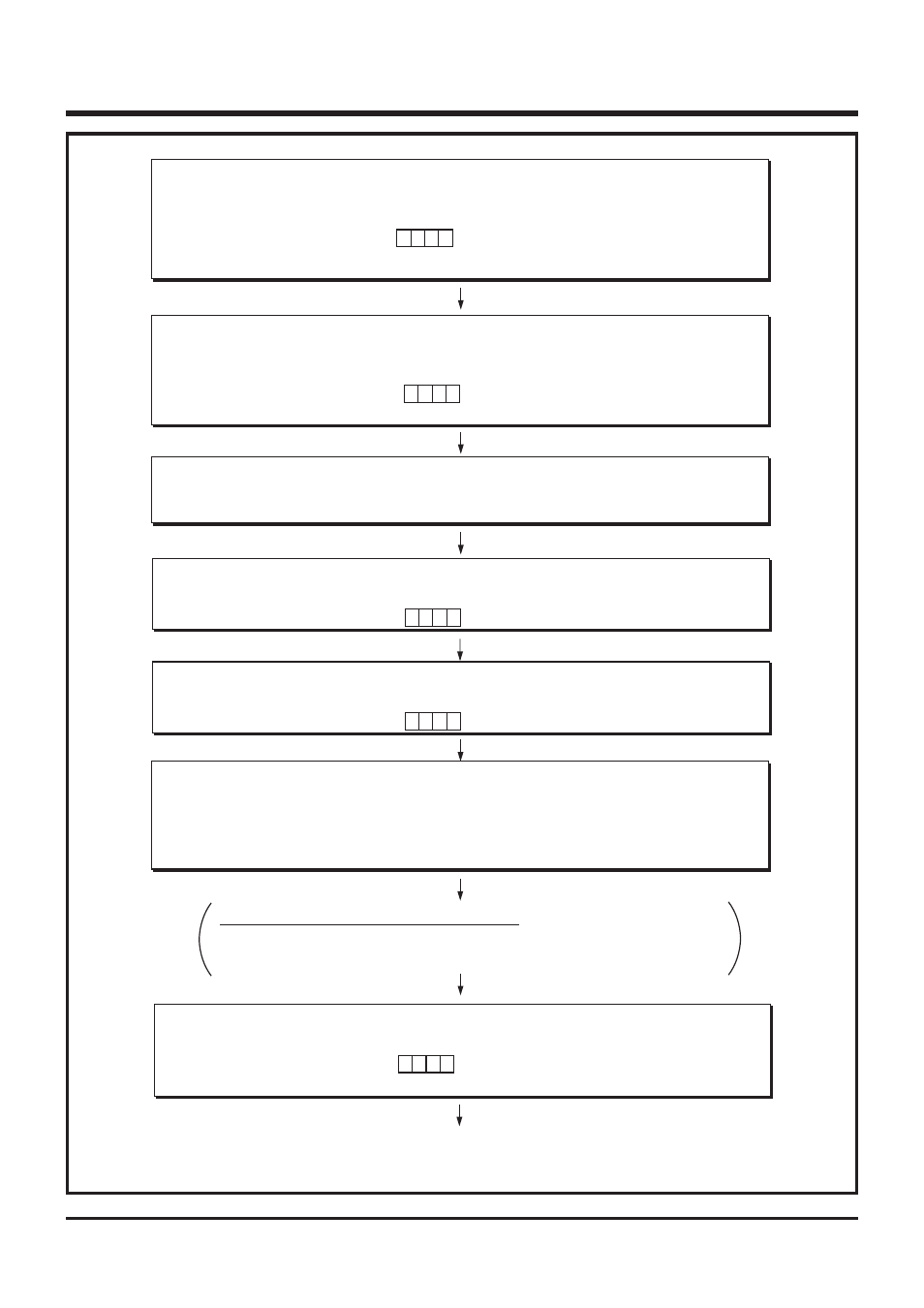
Fig. 2.3.7 Timer start by external input setting example (1)
0
b3
b0
➀
Disable Interrupts
Timer 1 interrupt is temporarily disabled.
Interrupt enable flag INTE
Interrupt control register V1
“0”
✕
✕
All interrupts disabled (DI instruction)
Timer 1 interrupt occurrence disabled
(TV1A instruction)
INT0 interrupt occurrence disabled
0
b3
b0
0 0
➁
Stop Timer Operation
Timer 1 and prescaler are temporarily stopped.
Dividing ratio of prescaler is selected.
Timer control register W1
✕
Timer 1 stop (TW1A instruction)
Prescaler stop
Prescaler divided by 4 selected
0
➂
Set Timer Value
Timer 1 count time is set.
Timer 1 reload register R1 “52
16
”
Timer count value 82 set (T1AB instruction)
b3
b0
1
➃
Set Port
P3
0
/INT0 pin is set to INT0 input.
Port P3
0
output latch
✕ ✕ ✕
INT0 input set (OP3A instruction)
b3
b0
1
➄
Set Valid Waveform
Valid waveform of INT0 pin is selected. Timer 1 control is enabled.
Interrupt control register I1
✕
Rising edge detected (TI1A instruction)
1 0
g0 h
➅
Clear Interrupt Request
Timer 1 interrupt activated condition is cleared.
INT0 interrupt activated condition is cleared.
Timer 1 interrupt request flag T1F
INT0 interrupt request flag EXF0
“0”
Timer 1 interrupt activated condition cleared
(SNZT1 instruction)
INT0 interrupt activated condition cleared
(SNZ0 instruction)
“0”
Note when the interrupt request is cleared
When
➅
is executed, considering the skip of the next instruction according to the
interrupt request flags T1F and EXF0, insert the NOP instruction after the SNZT1
and SNZ0 instructions.
b3
b0
1
➆
Enable Interrupts
The timer 1 interrupt which is temporarily disabled is enabled.
Interrupt control register V1
Interrupt enable flag INTE
“1”
Timer 1 interrupt occurrence enabled
(TV1A instruction)
All interrupts enabled (EI instruction)
✕
✕
✕
Timer start by external input
“
✕
”: it can be “0” or “1.”