7 reset, 1 reset circuit, Application – Renesas 4514 User Manual
Page 159
APPLICATION
2-56
4513/4514 Group User’s Manual
2.7 Reset
System reset is performed by applying “L” level to
the RESET
pin for 1 machine cycle or more when the
following conditions are satisfied:
the value of supply voltage is the minimum value or more of the recommended operating conditions
oscillation is stabilized.
Then when “H” level is applied to
RESET
pin, the software starts from address 0 in page 0 after elapsing
of the internal oscillation stabilizing time (f(X
IN
) is counted for 16892 to 16895 machine cycles). Figure 2.7.2
shows the oscillation stabilizing time.
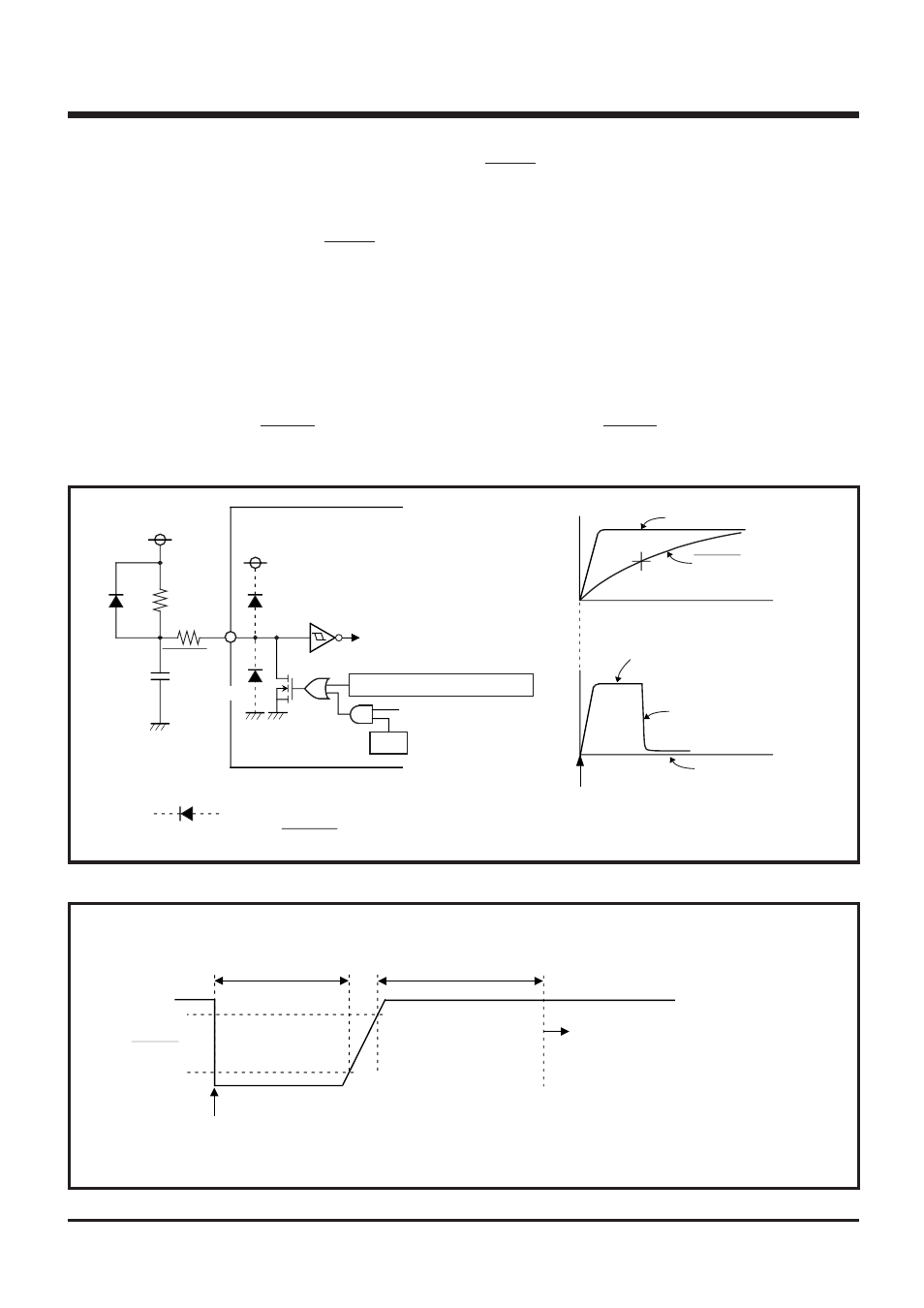
2.7.1 Reset circuit
The 4513/4514 Group has the power-on reset circuit and voltage drop detection circuit.
(1)
Power-on reset
Reset can be performed automatically at power on (power-on reset) by connecting resistors, a diode,
and a capacitor to RESET pin. Connect a capacitor between the RESET pin and V
SS
at the shortest
distance.
Fig. 2.7.1 Power-on reset circuit example
Fig. 2.7.2 Oscillation stabilizing time after system is released from reset
RESET
0.3V
DD
0.85V
DD
Software starts
(address 0 in page 0)
f(X
IN
)
is counted 16892 to
16895 times.
(Note)
Note: Keep the value of supply voltage to the minimum value
or more of the recommended operating conditions.
Reset input
1 machine cycle or more
=
2.7 Reset
V
D D
RESET pin
WEF
(Note)
Internal reset signal
Voltage drop detection circuit
Watchdog timer output
V
DD
RESET pin voltage
Power-on
Reset released
Internal reset signal
Reset state
Note:
This symbol represents a parasitic diode.
Applied potential to RESET pin must be V
DD
or less.
●
●