3 timer application examples, Application – Renesas 4514 User Manual
Page 133
APPLICATION
2.3 Timers
2-30
4513/4514 Group User’s Manual
2.3.3 Timer application examples
(1)
Timer operation: measurement of constant period
The constant period by the setting timer count value can be measured.
Outline: The constant period by the timer 1 underflow signal can be measured.
Specifications: Timer 1 and prescaler divides the system clock frequency f(X
IN
) = 4.0 MHz, and the
timer 1 interrupt request occurs every 3 ms.
Figure 2.3.3 shows the setting example of the constant period measurement.
(2)
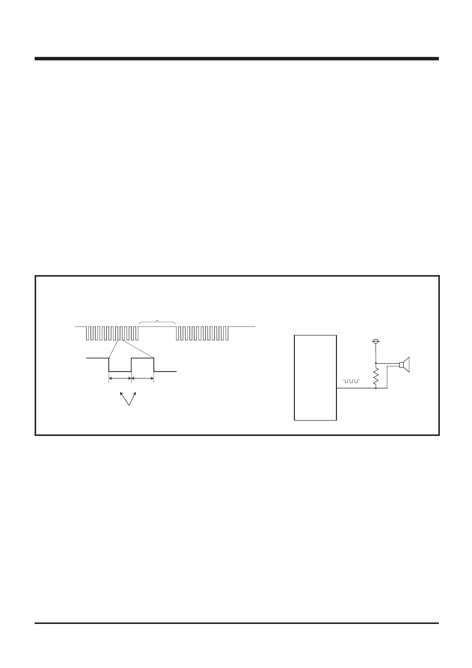
CNTR0 output operation: piezoelectric buzzer output
Outline: Square wave output from timer 1 can be used for piezoelectric buzzer output.
Specifications: 4 kHz square wave is output from the CNTR0 pin at system clock frequency f(X
IN
)
= 4.0 MHz. Also, timer 1 interrupt occurs simultaneously.
Figure 2.3.1 shows the peripheral circuit example, and Figure 2.3.4 shows the setting example of
CNTR0 output.
Fig. 2.3.1 Peripheral circuit example
(3)
CNTR0 input operation: event count
Outline: Count operation can be performed by using the signal (rising waveform) input from CNTR0
pin as the event.
Specifications: The low-frequency pulse from external as the timer 2 count source is input to CNTR0
pin, and the timer 2 interrupt request occurs every 100 counts.
Figure 2.3.5 shows the setting example of CNTR0 input.
4513/4514
CNTR0
125
µ
s125
µ
s
Set dividing ratio for timer 1 underflow cycle to 125
µ
s.
In order to reduce the current dissipation,
output is high-impedance state during buzzer
output stop.