2 a-d converter application examples, Application, 5 a-d converter – Renesas 4514 User Manual
Page 154
APPLICATION
2.5 A-D converter
2-51
4513/4514 Group User’s Manual
2.5.2 A-D converter application examples
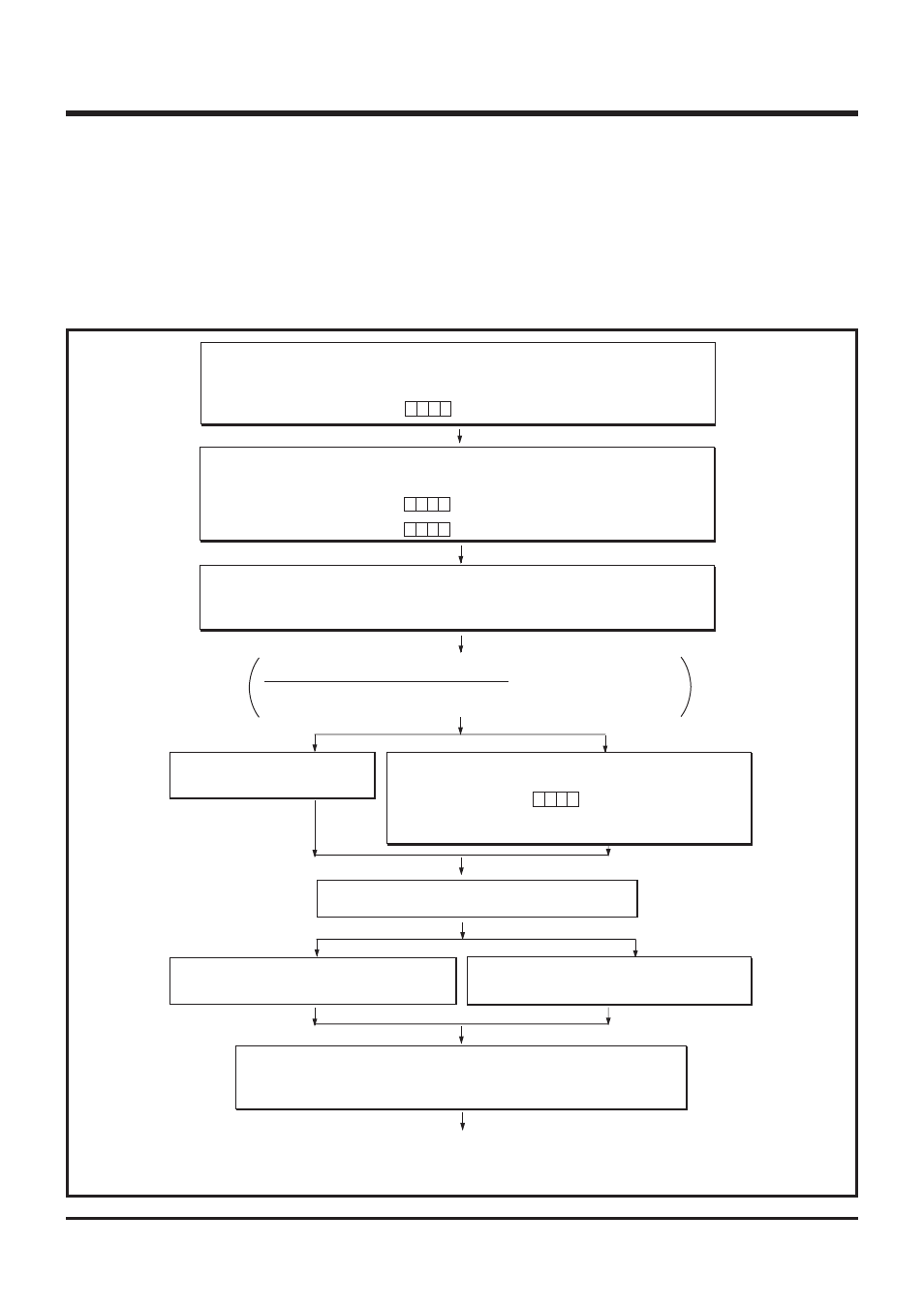
(1)
A-D conversion mode
Outline: Analog input signal from a sensor can be converted into digital values.
Specifications: Analog voltage values from a sensor is converted into digital values by using a 10-
bit successive comparison method. Use the A
IN0
pin for this analog input.
Figure 2.5.2 shows the A-D conversion mode setting example.
Fig. 2.5.2 A-D conversion mode setting example
b3
b0
➀
Disable Interrupts
A-D interrupt is temporarily disabled.
Interrupt enable flag INTE
Interrupt control register V2
“0”
✕
✕
All interrupts disabled (DI instruction)
A-D interrupt occurrence disabled
(TV2A instruction)
0
✕
➁
Set A-D Converter
A-D conversion mode is selected to A-D operation mode.
Analog input pin A
IN0
is selected.
A-D control register Q2
A-D conversion mode selected (TQ2A instruction)
A
IN0
selected (TQ1A instruction)
A-D control register Q1
b3
b0
✕
0
b3
b0
0 0
✕
0
✕ ✕
➂
Clear Interrupt Request
A-D interrupt activated condition is cleared.
A-D conversion completion flag ADF “0”
A-D conversion interrupt activated condition cleared
(SNZAD instruction)
Note when the interrupt request is cleared
When
➂
is executed, considering the skip of the next instruction according to the
flag ADF, insert the NOP instruction after the SNZAD instruction.
When interrupt is
not used
When interrupt is used
➃
Set Interrupt
Interrupts except A-D conversion is
enabled (EI instruction)
➃
Set Interrupt
A-D conversion interrupt temporarily disabled is enabled.
b3
b0
1
✕
✕ ✕
Interrupt control register V2
A-D interrupt occurrence enabled
(TV2A instruction)
Interrupt enable flag INTE “1”
All interrupts enabled
(EI instruction)
➄
Start A-D Conversion
A-D conversion operation is started (ADST instruction).
When interrupt is not used
When interrupt is used
➅
Check A-D Interrupt Request
A-D conversion completion flag is
checked (SNZAD instruciton)
➅
A-D Conversion Interrupt Occur
➆
Execute A-D Conversion
High-order 8 bits of register AD
→
register A and register B (TABAD instruction)
Low-order 2 bits of register AD
→
high-order 2 bits of register A (TALA instruction)
“0” is set to low-order 2 bits of register A
“
✕
”: it can be “0” or “1.”
When A-D conversion is executed by the same channel,
➄
to
➆
is repeated.
When A-D conversion is executed by the another channel,
➀
to
➆
is repeated.