5 notes on use, Application – Renesas 4514 User Manual
Page 151
APPLICATION
2.4 Serial I/O
2-48
4513/4514 Group User’s Manual
2.4.5 Notes on use
(1)
Note when an external clock is used as a synchronous clock:
• An external clock is selected as the synchronous clock, the clock is not controlled internally.
• Serial transfer is continued as long as an external clock is input. If an external clock is input 9 times
or more and serial transfer is continued, the receive data is transferred directly as transmit data,
so that be sure to control the clock externally.
Note also that the SIOF flag is set when a clock is counted 8 times.
• Make sure that the initial input level on the external clock pin is always “H” level.
• Table 2.4.2 shows the recommended operating conditions when using serial I/O with an external
clock. Figure 2.4.7 shows an input waveform of external clock.
Table 2.4.2 Recommended operating conditions (serial I/O)
Parameter
Serial I/O external clock period
(Note 1)
Condition
Middle-speed mode
High-speed mode
V
DD
= 4.0 V to 5.5 V
V
DD
= 2.5 V to 5.5 V
V
DD
= 2.0 V to 5.5 V (Note 2)
V
DD
= 4.0 V to 5.5 V
V
DD
= 2.5 V to 5.5 V
V
DD
= 2.0 V to 5.5 V (Note 2)
Limits
Min.
1.5
3.0
4.0
750
1.5
2.0
Max.
Unit
µ
s
ns
µ
s
Typ.
Notes 1: Limits shown in Table 2.4.2 represent the pulse widths of “H” and “L.”
2: It is effective only for mask version.
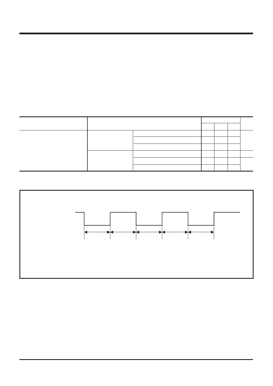
Fig. 2.4.7 Input waveform of external clock
External clock
input waveform
“L” pulse width “H” pulse width
Note: Set “H” and “L” pulse width for external waveform according to using
supply voltage and recommended operating conditions.