Function block operations, Hardware, 2) register a and carry flag – Renesas 4514 User Manual
Page 30: 3) registers b and e, 4) register d
4513/4514 Group User’s Manual
HARDWARE
1-17
FUNCTION BLOCK OPERATIONS
FUNCTION BLOCK OPERATIONS
CPU
(1) Arithmetic logic unit (ALU)
The arithmetic logic unit ALU performs 4-bit arithmetic such as 4-
bit data addition, comparison, AND operation, OR operation, and
bit manipulation.
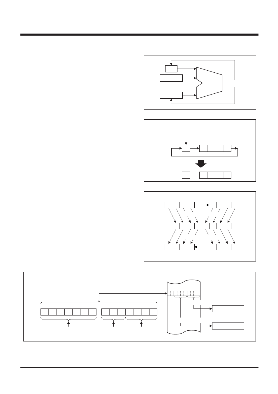
(2) Register A and carry flag
Register A is a 4-bit register used for arithmetic, transfer, ex-
change, and I/O operation.
Carry flag CY is a 1-bit flag that is set to “1” when there is a carry
with the AMC instruction (Figure 1).
It is unchanged with both A n instruction and AM instruction. The
value of A
0
is stored in carry flag CY with the RAR instruction (Fig-
ure 2).
Carry flag CY can be set to “1” with the SC instruction and cleared
to “0” with the RC instruction.
(3) Registers B and E
Register B is a 4-bit register used for temporary storage of 4-bit
data, and for 8-bit data transfer together with register A.
Register E is an 8-bit register. It can be used for 8-bit data transfer
with register B used as the high-order 4 bits and register A as the
low-order 4 bits (Figure 3).
(4) Register D
Register D is a 3-bit register.
It is used to store a 7-bit ROM address together with register A and
is used as a pointer within the specified page when the TABP p,
BLA p, or BMLA p instruction is executed (Figure 4).
Fig. 1 AMC instruction execution example
Fig. 2 RAR instruction execution example
Fig. 3 Registers A, B and register E
Fig. 4 TABP p instruction execution example
(CY)
(M(DP))
(A)
Addition
ALU
CY
A
3
A
2
A
1
A
0
A
0
CY A
3
A
2
A
1
RAR instruction
SC instruction
RC instruction
A
3
A
2
A
1
A
0
B
3
B
2
B
1
B
0
E
7
E
6
E
5
E
4
E
3
E
2
E
1
E
0
A
3
A
2
A
1
A
0
B
3
B
2
B
1
B
0
TAB instruction
TEAB instruction
TABE instruction
TBA instruction
Register B
Register A
Register B
Register A
Register E
Specifying address
TABP p instruction
p
6
p
5
p
4
p
3
p
2
p
1
p
0
PC
H
DR
2
DR
1
DR
0
A
3
A
2
A
1
A
0
PC
L
Immediate field
value p
The contents of
register D
ROM
8
4
0
Middle-order 4 bits
Low-order 4bits
Register A (4)
Register B (4)
The contents of
register A