Application, 2 interrupts, Set port – Renesas 4514 User Manual
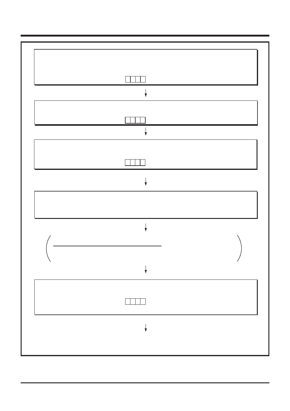
Page 121: Disable interrupts, Set valid waveform, Clear interrupt request, Enable interrupts, Int0 interrupt execution started
APPLICATION
2.2 Interrupts
2-18
4513/4514 Group User’s Manual
Fig. 2.2.2 INT0 interrupt setting example
Note: The valid waveforms causing the interrupt must be retained at their level for 4 cycles or more
of system clock.
➁
Set Port
Port used for INT0 interrupt is set to input port.
0
b3
b0
b3
b0
✕
1
✕
✕
Both edges detection selected (TI1A instruction)
b3
b0
1
1
b3
b0
➀
Disable Interrupts
INT0 interrupt is temporarily disabled.
Interrupt enable flag INTE
Interrupt control register V1
“0”
✕ ✕ ✕
All interrupts disabled (DI instruction)
INT0 interrupt occurrence disabled
(TV1A instruction)
Port P3
0
output latch
✕ ✕ ✕
Set to input (OP3A instruction)
➂
Set Valid Waveform
Valid waveform of INT pin is selected.
Both edges detection selected
Interrupt control register I1
➃
Clear Interrupt Request
External interrupt activated condition is cleared.
INT0 interrupt request flag EXF0
“0”
INT0 interrupt activated condition cleared
(SNZ0 instruction)
Note when the interrupt request is cleared
When
➃
is executed, considering the skip of the next instruction according to the
interrupt request flag EXF0, insert the NOP instruction after the SNZ0 instruction.
➄
Enable Interrupts
The INT0 interrupt which is temporarily disabled is enabled.
Interrupt control register V1
Interrupt enable flag INTE
“1”
✕ ✕ ✕
INT0 interrupt occurrence enabled
(TV1A instruction)
All interrupts enabled (EI instruction)
INT0 interrupt execution started
“
✕
”: it can be “0” or “1.”