Paradyne CSU User Manual
Page 67
4. Configuration Options
9128-A2-GB20-80
September 2002
4-23
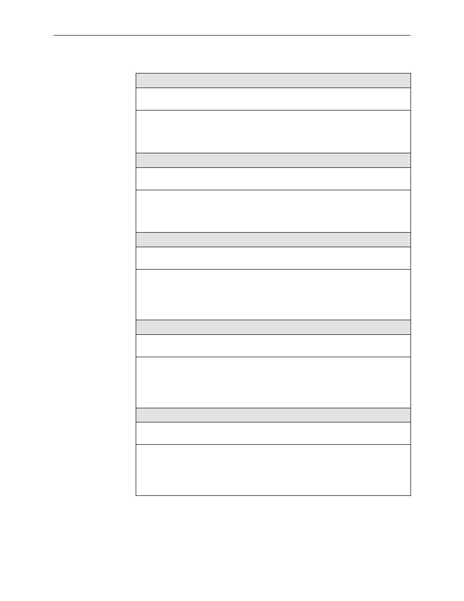
LMI Error Event (N2)
Possible Settings: 1, 2, 3, 4, 5, 6, 7, 8, 9, 10
Default Setting: 3
Configures the LMI-defined N2 parameter, which sets the number of errors that can occur
on the LMI link before an error is reported. Applies to both the user and network sides of a
UNI.
1 – 10 – Specifies the maximum number of errors.
LMI Clearing Event (N3)
Possible Settings: 1, 2, 3, 4, 5, 6, 7, 8, 9, 10
Default Setting: 1
Configures the LMI-defined N3 parameter, which sets the number of error-free messages
that must be received before clearing an error event. Applies to both the user and network
sides of a UNI.
1 – 10 – Specifies how many error-free messages it will take to clear the error event.
LMI Status Enquiry (N1)
Possible Settings: 1, 2, 3, 4, . . . 255
Default Setting: 6
Configures the LMI-defined N1 parameter, which sets the number of status enquiry polling
cycles that the user side of the LMI initiates before a full status enquiry is initiated. Applies
to the user side of a UNI only.
1 – 255 – Specifies the number of status enquiry polling cycles that can be initiated before
a full status enquiry is initiated.
LMI Heartbeat (T1)
Possible Settings: 5, 10, 15, 20, 25, 30
Default Setting: 10
Configures the LMI-defined T1 parameter, which sets the number of seconds between the
initiation of status enquiry messages on the user side of the LMI. Applies to the user side
of a UNI only.
5 – 30 – Specifies the number of seconds between the initiation of status enquiry
messages in increments of 5.
LMI Inbound Heartbeat (T2)
Possible Settings: 5, 10, 15, 20, 25, 30
Default Setting: 15
Configures the LMI-defined T2 parameter, which sets the number of seconds between the
receipt of status enquiry messages on the network side of the LMI. Applies to the network
side of a UNI only.
5 – 30 – Specifies the number of seconds between the receipt of status enquiry messages
in increments of 5.
Table 4-1.
System Frame Relay and LMI Options (3 of 4)