Com port connector, Com port for 9126 and 9128-ii (25-position), Com port for 9126-ii (9-position) – Paradyne CSU User Manual
Page 426
E. Connectors, Cables, and Pin Assignments
E-4
September
2002
9128-A2-GB20-80
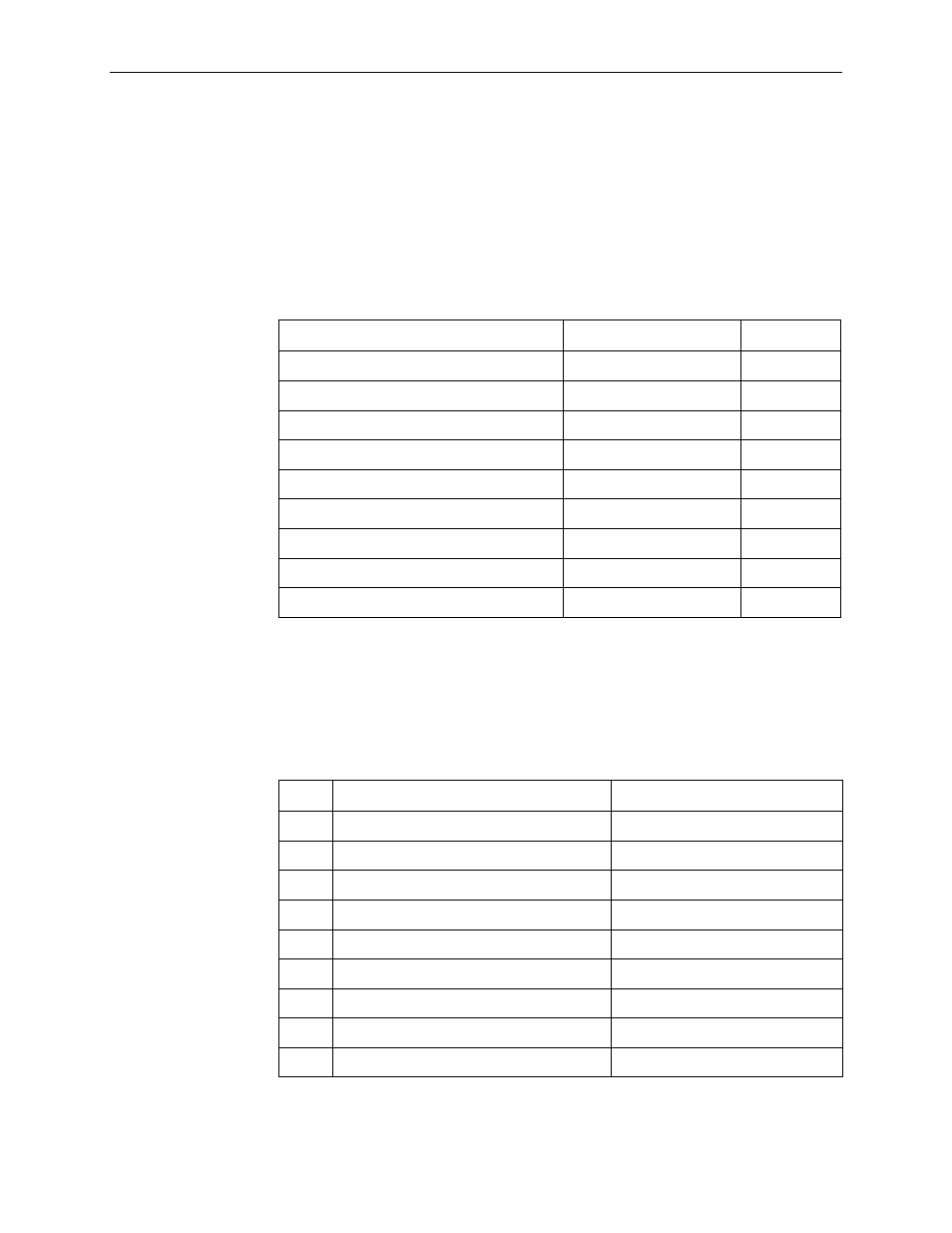
COM Port Connector
The type of COM port connector depends on the model.
COM Port for 9126 and 9128-II (25-Position)
The following table provides the pin assignments for the FrameSaver SLV 9126
and 9128-II units’ 25-position EIA-232C communication port connector.
COM Port for 9126-II (9-Position)
The following table provides the pin assignments for the 1-slot FrameSaver
SLV 9126-II’s 9-position EIA-232C communication port connector.
Signal
Direction
Pin #
Shield (GND)
—
1
DCE Transmit Data (TXD)
From DTE ( In )
2
DCE Receive Data ( RXD)
To DTE ( Out)
3
DCE Request to Send ( RTS)
From DTE ( In )
4
DCE Clear to Send (CTS)
To DTE (Out )
5 *
DCE Data Set Ready (DSR)
From DTE ( In )
6*
Signal Ground ( SG)
—
7
DCE Carrier Detect ( CD)
To DTE ( Out)
8*
DCE Data Terminal Ready (DTR)
From DTE ( In )
20
* Pins 5, 6, and 8 are tied together.
Pin #
Signal
Direction
1*
Data Carrier Detect (D CD)
To DTE ( Out)
2
Receive Data (RD)
To DTE ( Out)
3
Transmit Data ( TD)
From DTE (In )
4
Data Terminal Ready (DTR)
From DTE ( In )
5
Signal Ground (GND)
—
6*
Data Set Ready ( DSR)
To DTE ( Out)
7
Not used
—
8*
Clear To Send (CTS)
To DTE ( Out)
9
Not used
—
*Pins 1, 6, and 8 are tied together.