Led descriptions – Paradyne CSU User Manual
Page 190
7. Operation and Maintenance
7-8
September
2002
9128-A2-GB20-80
LED Descriptions
Table 7-1, General Status LEDs
, identifies the alarms that cause the Alarm LED to
Table 7-2, Network, DSX, or PRI Interface LEDs
, for network, DSX-1,
and PRI interface LED information,
Table 7-3, User Data Port LED (CSU/DSUs
, for user data port interface LED information, and
for Ethernet interface LED information.
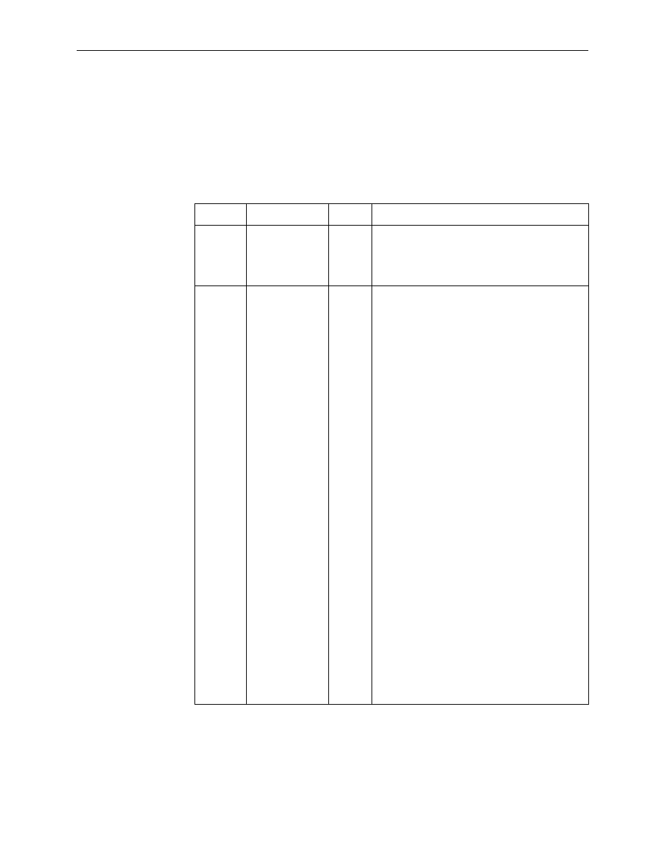
Table 7-1.
General Status LEDs (1 of 2)
Label
Indiction
Color
What It Means
OK
1
Power and
Operational
Status
Green
ON – FrameSaver unit has power and it is
operational.
OFF – FrameSaver unit is in a power-on
self-test, or there is a failure.
ALM Operational
Alarm ( Fail)
Red
ON – FrameSaver unit has just been reset, or an
error or fault has been detected.
Error/fault/alarm conditions:
T
Alarm Indication Signal (AIS)
T
CTS Down
T
DBM BRI Card Failure
T
DBM Download Failed
T
DLCI Down
T
DTR Down
T
Ethernet Link Down
T
Exceeded Error Rate (EER)
T
Internal Modem Failed
T
ISDN Network Failed
T
LMI Down
T
Loss of Signal (LOS)
T
Network Communication Link Down
T
Out of Frame ( OOF)
T
Power Supply/Fan Failure
T
Primary or Secondary Clock Failed
T
Self-Test Failed
T
SLV Latency Exceeded
T
SLV Timeout
T
Suboptimal Link Rate
T
Two Level-1 Users Accessing Device
T
Yellow Alarm Signal
1
When an ISDN BRI DBM is installed, if the OK LED comes on then goes off during
power recycling, the ISDN BRI DBM may have failed.
2
On the Display LEDs & Control Leads screen for the Model 9128-II only, FR Mode
is On or Off. When On (highlighted), the FrameSaver unit is in Frame Relay mode.