Nperforming scan operations automatically – Konica Minolta Polygon Editing Tool User Manual
Page 92
90
Chapter
2
File
Menu
900
910
File – Import – Digitizer – Step Scan (When VIVID 900/910 is Selected)
n
Performing Scan Operations Automatically
If the bench top frame set is used and calibration chart data exists, a series of scan operations can be pro-
cessed automatically.
1
From the [File] menu, select [Import],
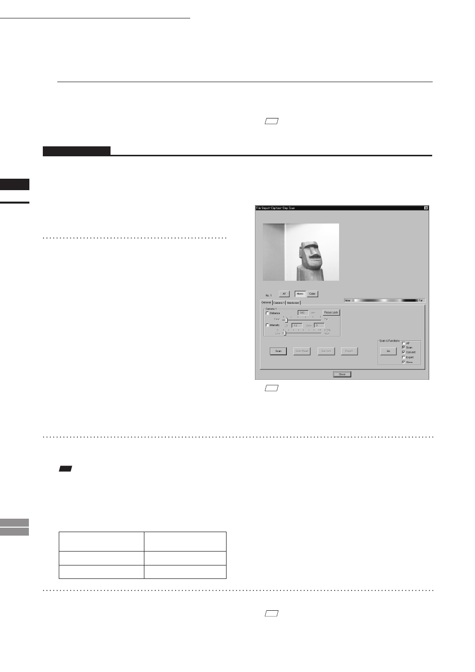
[Digitizer] and then [Step Scan].
The [File-Import-Digitizer-Step Scan] dialog
box will appear.
2
Select the desired installation direction
of the VIVID digitizer.
From the [Hardware] tab, check the [Bench
Top Frame set] checkbox, and select the VIVID
digitizer installation direction by clicking the
corresponding [Mounted] radio button.
Check the [Auto Scan] checkbox under the
[Hardware] tab.
Select [Vertical] if the VIVID digitizer is
mounted vertically, or select [Horizontal] if it is
mounted horizontally.
• The monochrome monitor image currently cap-
tured by the VIVID 910 or VIVID 900 will ap-
pear in the image area of the dialog box.
M
emo
If the VIVID digitizer is mounted horizontally, the pre-
view image will be in portrait form.
After the image is converted to 3D, it will be displayed ac-
cording to the coordinate system of the VIVID.
M
emo
For details of how to save the calibration chart data, refer
to page 87,88.
Operating Procedure
3
Place the object on the rotating stage.
Note
If the VIVID digitizer is mounted on the frame set hori-
zontally, the object will be affected by repeated reflection
on the rotating stage surface, preventing correct scan
operation. To prevent this, place an appropriate item of
the following thickness under the object to raise it.
Measurement
Distance
Thickness of Item
600 mm
Approx. 30 mm
1000 mm
Approx. 20 mm
4
To display the object in the middle of the
image area, change the position of the
object or move the rotating stage back
and forth to change the view angle.
M
emo
If necessary, replace the lens attached to the VIVID
digitizer.