Indivisible cycles, Indivisible cycles -52, Table 1-15. single-cycle instructions -52 – Motorola MVME1X7P User Manual
Page 78
1-52
Computer Group Literature Center Web Site
Programming Issues
1
DS1 goes inactive). This time should be longer than any expected
legitimate transfer time on the bus. We normally set it to 256
µ
sec. This
timer can also be disabled for debug purposes.
Before a single-board computer access to another single-board computer
can complete, however, the VMEchip2 on the accessed board must decode
a slave access and request the Local Bus of the second board. When the
Local Bus is granted (any in-process onboard transfers have completed),
then the Local Bus timer of the accessed board starts. Normally, this is also
set to 8
µ
sec. When the memory has the data available, a transfer
acknowledge signal (TA) is given. This translates into a DTACK signal on
the VMEbus which is then translated into a TA signal to the first requesting
processor, and the transfer is complete.
If the VMEbus global timer expires on a legitimate transfer, the VMEbus
to Local Bus controller in the VMEchip2 may become confused and the
VMEchip2 may misbehave. Therefore the bus timer values must be set
correctly. The correct settings may depend on the system configuration.
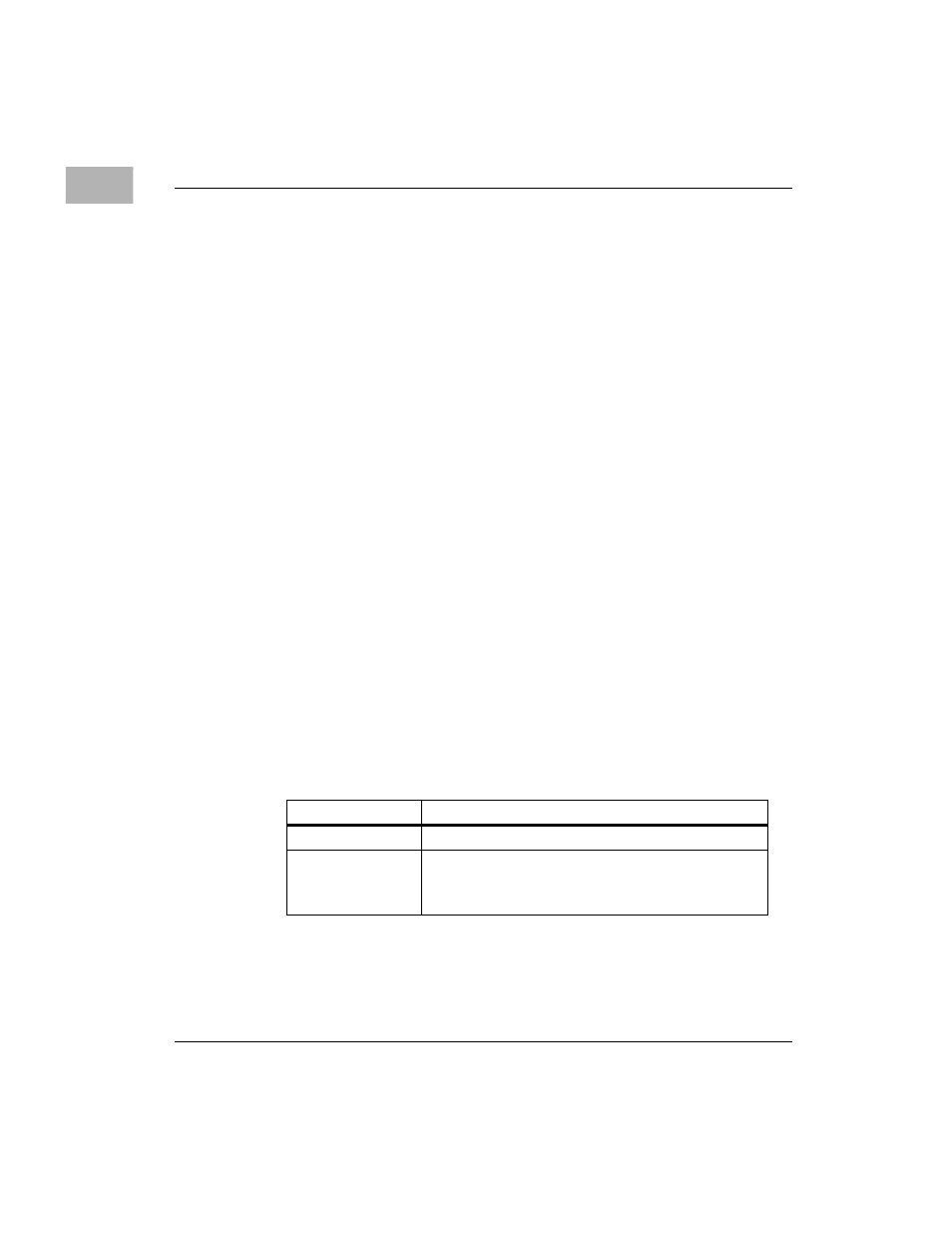
Indivisible Cycles
The MVME167P and MVME177P single-board computers perform
operations that require indivisible read-modify-write (RMW) memory
accesses. These RMW sequences occur when the MMU modifies table
entries or when the MPU executes one of the single-cycle instructions
listed in Table
.
Table 1-15. Single-Cycle Instructions
MPU
Instructions
MC68040
CAS, CAS2, TAS
MC68060
CAS
CAS2 and misaligned CAS instructions are emulated
by software (see NOTE)