Table 1-3. local bus memory map -21 – Motorola MVME1X7P User Manual
Page 47
Memory Maps
http://www.motorola.com/computer/literature
1-21
1
The onboard I/O space must be marked cache-inhibit and serialized in its
page table.
further defines the map for the local I/O
devices on the MVME1X7P.
Notes
1. ROM on MVME167P, ROM/Flash on MVME177P. Flash/EPROM
devices appear at $FF800000 - $FFBFFFFF, and also appear at
$00000000 - $003FFFFF if the ROM0 bit in the VMEchip2
EPROM control register is high (ROM0 = 1).
The ROM0 bit is located at address $FFF40030 bit 20. ROM0 is set
to 1 after each reset. The ROM0 bit must be cleared before other
resources (DRAM or SRAM) can be mapped in this range
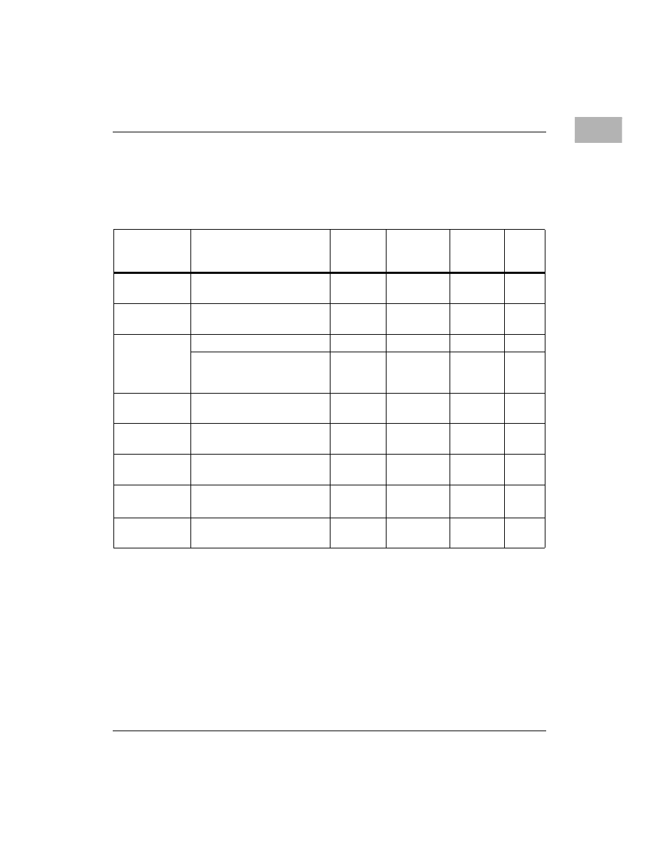
Table 1-3. Local Bus Memory Map
Address
Range
Devices Accessed
Port Size
Size
Software
Cache
Inhibit
Notes
$00000000 -
DRAMSIZE
User Programmable
(Onboard SDRAM)
D32
DRAMSIZE
N
1, 2
DRAMSIZE -
$FF7FFFFF
User Programmable
(VMEbus)
D32/D16
3GB
?
3, 4
$FF800000 -
$FFBFFFFF
ROM (167P)
D32
4MB
N
1
EPROM/Flash (177P)
D32
2MB
EPROM,
4MB Flash
N
1,6
$FFC00000 -
$FFDFFFFF
Reserved
--
2MB
--
5
$FFE00000 -
$FFE1FFFF
SRAM
D32
128KB
N
--
$FFE20000 -
$FFEFFFFF
SRAM (repeated)
D32
896KB
N
--
$FFF00000 -
$FFFEFFFF
Local I/O Devices
(Refer to next table)
D32-D8
1MB
Y
3
$FFFF0000 -
$FFFFFFFF
User Programmable
(VMEbus A16)
D32/D16
64KB
?
2, 4