Programming the tick timers, Tick timer 1 compare register, Programming the tick timers -18 – Motorola MVME1X7P User Manual
Page 216: Tick timer 1 compare register -18
3-18
Computer Group Literature Center Web Site
PCCchip2
3
A suggested setting of the Local Interrupt Vector Register in the SCC chip
is $5C. This produces the following vectors:
Programming the Tick Timers
This section provides addresses and bit level descriptions of the prescaler,
tick timers, and various other timer registers.
Tick Timer 1 Compare Register
The Tick Timer 1 Compare Register is a 32-bit register located at
$FFF42004. The count value of Tick Timer 1 is compared to this register.
When they are equal, an interrupt is sent to the Local Bus interrupter and
the overflow counter is incremented. If the clear-on-compare mode is
enabled, the counter is also cleared. For periodic interrupts, the following
equation should be used to determine the compare register value for a
specific period.
compare register value = T (
µ
s)
When programming the tick timer for periodic interrupts, the counter
should be cleared to zero by software and then enabled. If the counter does
not initially start at zero, the time to the first interrupt may be longer or
shorter than expected. The rollover time for the counter is 71.6 minutes.
$5C
Serial RX Exception IRQ
$5D
Serial Modem IRQ
$5E
Serial TX IRQ
$5F
Serial RX IRQ
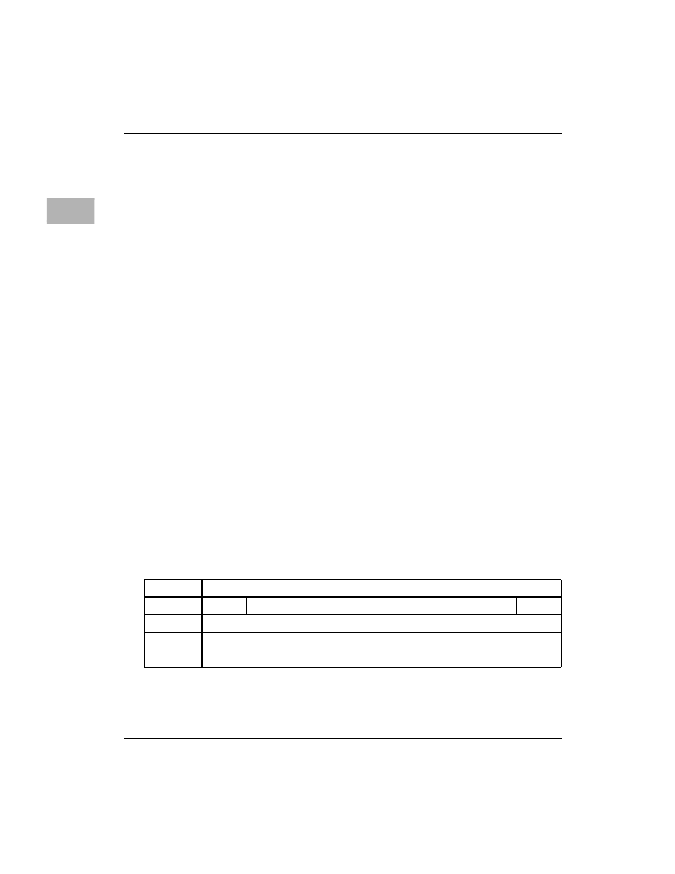
ADR/SIZ
$FFF42004 (32 bits)
BIT
31
. . .
0
NAME
Tick Timer 1 Compare Register
OPER
R/W
RESET
0 P