Tick timer 1 interrupt control register, Tick timer 1 interrupt control register -26 – Motorola MVME1X7P User Manual
Page 224
3-26
Computer Group Literature Center Web Site
PCCchip2
3
INT
Interrupt Status. When this bit is high a Tick Timer 2
interrupt is being generated at the level programmed in
IL2-IL0 (if nonzero). This bit is edge-sensitive and can be
cleared by writing a logic 1 into the ICLR control bit.
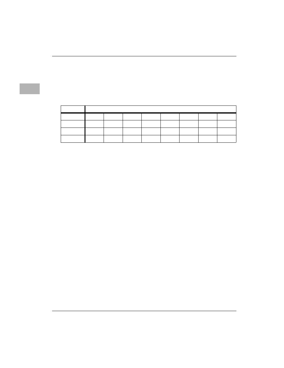
Tick Timer 1 Interrupt Control Register
IL2-IL0
Interrupt Request Level. These three bits select the
interrupt level for Tick Timer 1. Level 0 does not generate
an interrupt.
ICLR
Writing a logic 1 into this bit clears the INT status bit.
This bit is always read as zero.
IEN
Interrupt Enable. When this bit is high, the interrupt is
enabled. The interrupt is disabled when this bit is low.
INT
Interrupt Status. When this bit is high a Tick Timer 1
interrupt is being generated at the level programmed in
IL2-IL0 (if nonzero). This bit is edge-sensitive and can be
cleared by writing a logic 1 into the ICLR control bit.
ADR/SIZ
$FFF4201B (8 bits)
BIT
7
6
5
4
3
2
1
0
NAME
INT
IEN
ICLR
IL2
IL1
IL0
OPER
R
R
R
R/W
C
R/W
R/W
R/W
RESET
0
0
0 PL
0 PL
0 PL
0 PL
0 PL
0 PL