Printer busy interrupt control register, Printer busy interrupt control register -43 – Motorola MVME1X7P User Manual
Page 241
Programming Model
http://www.motorola.com/computer/literature
3-43
3
Printer BUSY Interrupt Control Register
IL2-IL0
These three bits select the interrupt level for the printer
BUSY. Level 0 does not generate an interrupt.
ICLR
In edge-sensitive mode, writing a logic 1 to this bit clears
the INT status bit. This bit has no function in level-
sensitive mode. This bit is always read as zero.
IEN
When this bit is high, the interrupt is enabled. The
interrupt is disabled when this bit is low.
INT
When this bit is high, a printer BUSY interrupt is being
generated at the level programmed in IL2-IL0 (if
nonzero).
E/L*
When this bit is high, the interrupt is edge-sensitive. The
interrupt is level-sensitive when this bit is low.
PLTY
When this bit is low, interrupt is activated by a rising
edge/high level of the BUSY pin.
When this bit is high, interrupt is activated by a falling
edge/low level of the BUSY pin.
Note that if this bit is changed while the E/L* bit is set (or
is being set), a BUSY interrupt may be generated. This
can be avoided by setting the ICLR bit during write cycles
that change the E/L* bit.
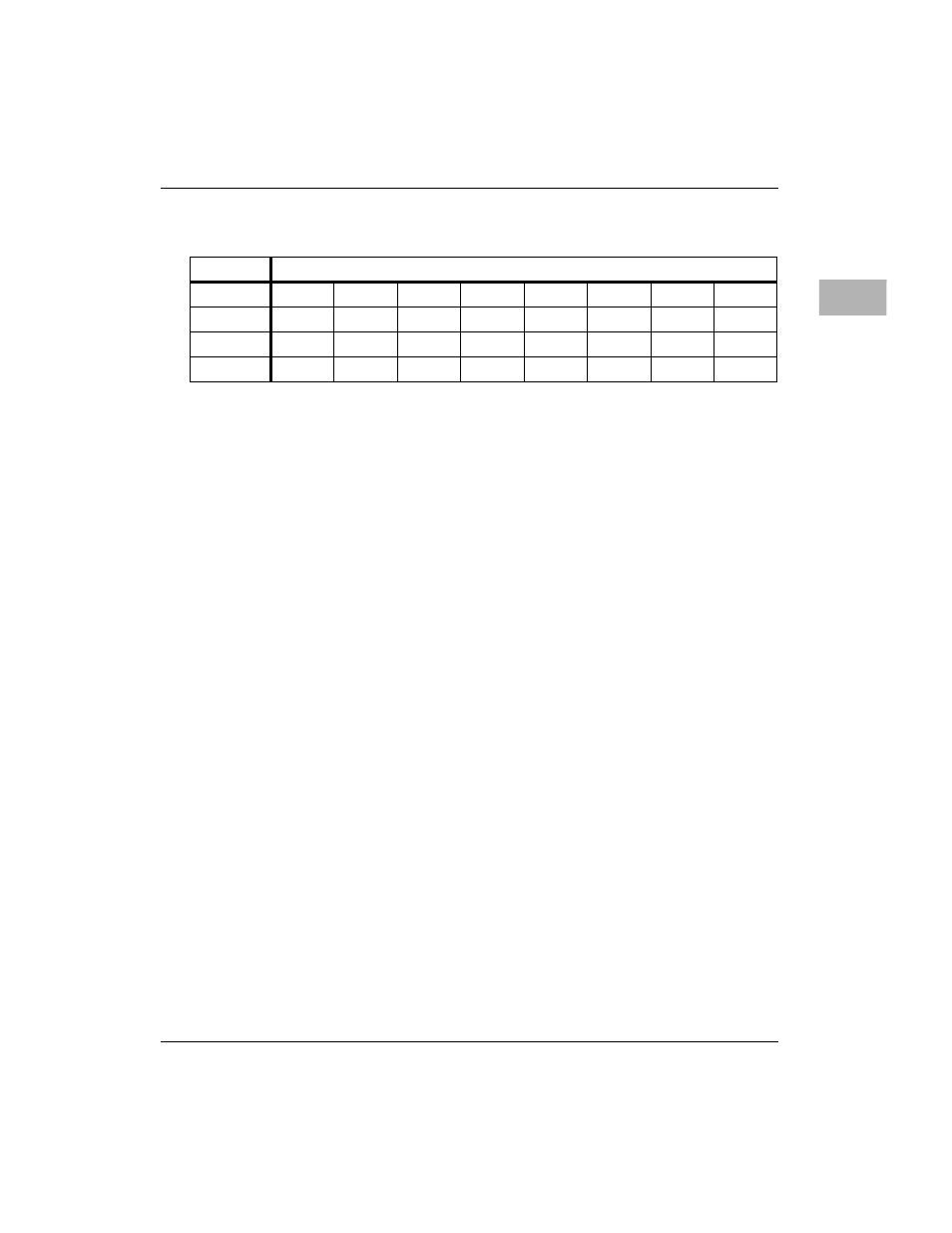
ADR/SIZ
$FFF42034 (8 bits)
BIT
31
30
29
28
27
26
25
24
NAME
PLTY
E/L*
INT
IEN
ICLR
IL2
IL1
IL0
OPER
R/W
R/W
R
R/W
C
R/W
R/W
R/W
RESET
0 PL
0 PL
0 PL
0 PL
0 PL
0 PL
0 PL
0 PL