Sample program sequence, Figure 5-9 can communication flowchart – FUJITSU CAN-Motor Board MB91F267N User Manual
Page 99
AN07-00180-3E
- 99 -
5.4.2
Sample program sequence
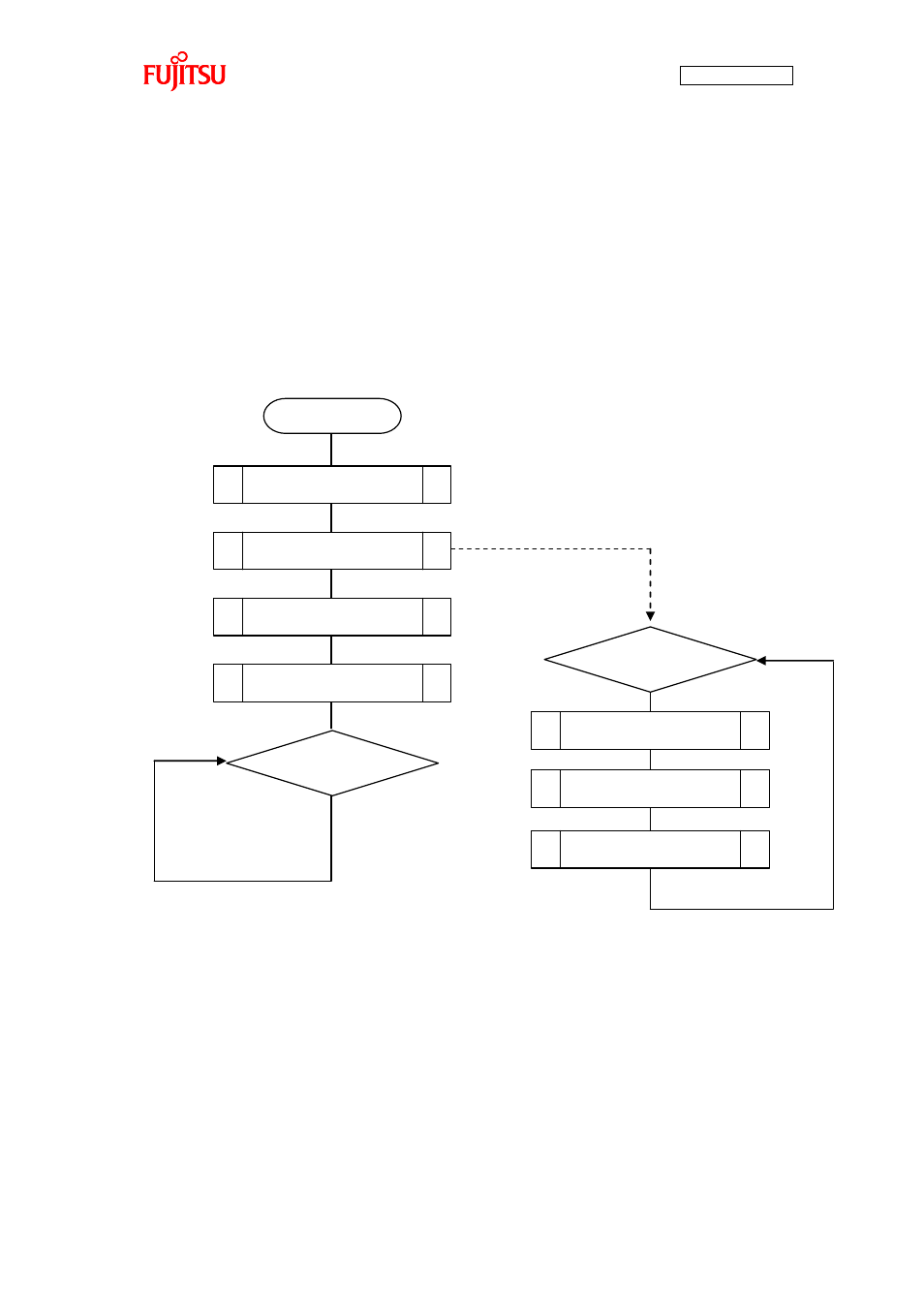
“Figure 5-9 CAN communication flowchart” shows the CAN communication sequence of the sample
program flow. First, the microcontroller is initialized. On the microcontroller initialization, the CAN
operation timer starts operating.
After that, the CAN driver is initialized. Then, the motor driving macro is initialized and then the program
goes into a loop.
Subsequently, motor rotation information transmit, temperature sensor information transmit, receive
processing are handled in the timer routine.
Figure 5-9 CAN communication flowchart
Microcontroller initialization
Motor macro initialization
Start
Infinite loop
CAN operation timer running
Timer is running
Receive processing
CAN driver initialization
Motor rotation info transmit
Receive processing
- XG Series P3NK-4452-01ENZD (614 pages)
- FPCAC14C (1 page)
- MCJ3230SS (161 pages)
- MBA3073NC (138 pages)
- T5140 (102 pages)
- T5140 (76 pages)
- MAM3367MC/MP (152 pages)
- MPC3045AH (185 pages)
- MB2142-02 (23 pages)
- MB15F86UL (6 pages)
- MHS2030AT (40 pages)
- MHW2100BS (296 pages)
- MHK2060AT (227 pages)
- Disk Drives MHK2060AT (227 pages)
- MCM3064SS (170 pages)
- Mainboard D1561 (45 pages)
- MHC2040AT (219 pages)
- D1961 (45 pages)
- DISK DRIVES MHM2100AT (231 pages)
- MHR2010AT (250 pages)
- MHZ2120BJ (320 pages)
- MCE3064AP (175 pages)
- LQFP-64P (16 pages)
- Solaris PCI GigabitEthernet 3.0 (115 pages)
- MAY2036RC (94 pages)
- MAB3091 (142 pages)
- MPE3XXXAT (191 pages)
- MHV2040AH (40 pages)
- MHW2040AC (278 pages)
- ETERNUSmgr P2X0-0202-01EN (64 pages)
- VSS Hardware Provider 2.1 (134 pages)
- MAG3182FC (61 pages)
- MAU3147NC/NP (130 pages)
- MAX3147RC (94 pages)
- MHV2160BT (296 pages)
- MHV2040AT (280 pages)
- MAW3300NC/NP (130 pages)
- DeskPower E623 (50 pages)
- MAG3182LC (133 pages)
- OPTICAL DISK DRIVES MDG3064UB (42 pages)
- MHF2021AT (225 pages)
- MHR2040AT (40 pages)
- Single Drive FTM7926FB (1 page)
- PG-FCS103 (98 pages)
- MAS3735FC (114 pages)