Table 5-2 – FUJITSU CAN-Motor Board MB91F267N User Manual
Page 94
AN07-00180-3E
- 94 -
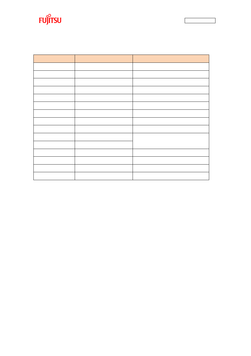
Table 5-2 Description of the entire CAN communication control registers and setting values
Register name
Setting value [function]
Description
CTRLR0_Test
0 [normal operation]
Test mode enable bit
CTRLR0_CCE
1 [write enable]
Bit timing register write enable bit
CTRLR0_DAR
0 [automatic retransmit enable]
Automatic retransmit prohibit bit
CTRLR0_EIE
0 [code setting disable]
Error interrupt code enable bit
CTRLR0_SIE
0 [code setting disable]
Status interrupt code enable bit
CTRLR0_IE
0 [interrupt disable]
Interrupt enable bit
CTRLR0_Init
1 [initialization]
Initialization bit
BTR0
0x2B43 [250 Kbps]
CAN communication speed
TESTR0_Rx
0 [dominant]
RXO pin monitor bit
TESTR0_Tx1
0 [normal operation]
TXO pin control bits
TESTR0_Tx0
0 ↑
TESTR0_LBack
0 [loopback mode disable]
Loopback mode
TESTR0_Silent
0 [silent mode disable]
Silent mode
TESTR0_Basic
0 [basic mode disable]
Basic mode
BRPER0_BRPE
0 [value added to BTR0]
Baud rate prescaler extension bit
The registers used for CAN communication message handling on the microcontroller are APIs of the
CAN driver in the sample software, so descriptions of the following registers are omitted. For more
information of the registers, refer to the microcontroller hardware manual.
■Message interface registers
- IFx command request register (IFxCREQ)
- IFx command mask register (IFxCMSK)
- IFx mask register 1, 2 (IFxMSK1, IFxMSK2)
- IFx arbitration register 1, 2 (IFxARB1, IFxARB2)
- IFx message control register (IFxMCTR)
- IFx data register A1, A2, B1, B2 (IFxDTA1, IFxDTA2, IFxDTB1, IFxDTB2)
■Message handler registers
- CAN transmit request register 1, 2 (TREQR1, TREQR2)
- CAN data update register 1, 2 (NEWDT1, NEWDT2)
- CAN interrupt pending register 1, 2 (INTPND1, INTPND2)
- CAN message enable register 1, 2 (MSGVAL1, MSGVAL2)