FUJITSU CAN-Motor Board MB91F267N User Manual
Page 15
AN07-00180-3E
- 15 -
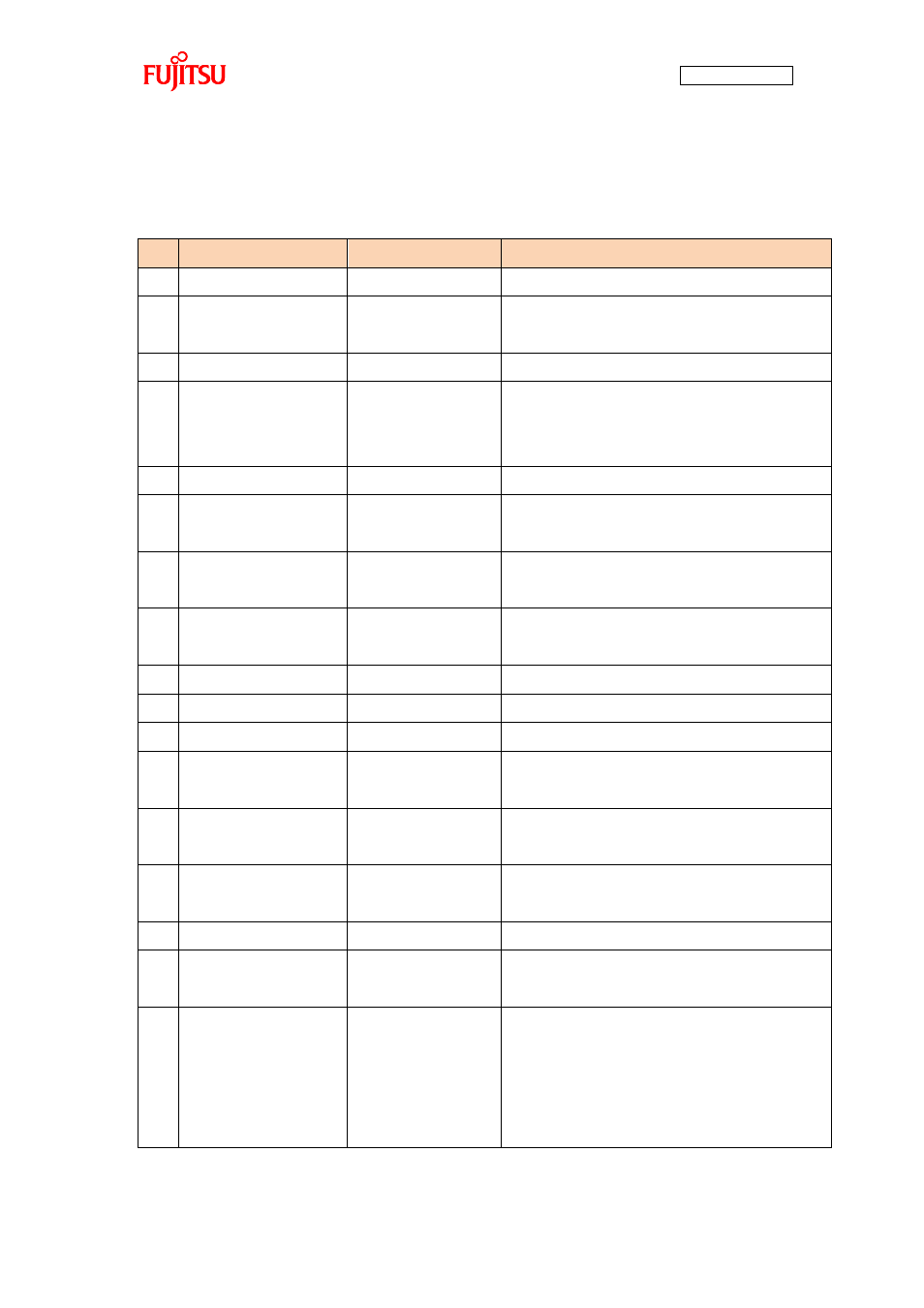
“Table 1-2 Description of the respective board parts” provides descriptions of the respective board parts.
Table 1-2 Description of the respective board parts
No.
Name
Function
Description
(1)
Target device
MB91F267N
Main microcontroller (MB91F267N).
(2)
Target device oscillator
CSTCR4M00G15C
Ceralock made by Murata Manufacturing
Oscillator for the main microcontroller.
(3)
CAN transceiver
MAX3058ASA+
Transceiver IC for CAN communication.
(4)
CAN connector
3-pin connector
Connector for CAN communication.
Connect this connector to the CAN connector on the
bits pot white.
(5)
USB to UART converter
FT232RL
IC for conversion between UART and USB.
(6)
USB connector
miniB
USB connector for connection with the PC to
write/debug a program.
(7)
Motor driver circuit
3-phase motor driver
circuit
Driver circuit for 3-phase motor operation by the main
microcontroller.
(8)
Motor connector
8 pins
Connector for connection with the 3-phase motor
included in the kit.
(9)
DC jack
-
Power connector for the operation of the motor.
(10)
Mode SW
Slide switch
Switch for selection of operation mode of the board.
(11)
Reset SW
Push switch
Switch to reset the board.
(12)
Test switches
Push switch x 2
Slide switch x 1
Connected to the general-purpose I/O port.
The sample program uses this switch for motor rotation.
(13)
LED lamps
LED (green) x 6
LED (red) x 3
General-purpose LED lamps.
(14)
Temperature sensor
NTCG164BH103
NTC thermistor made by TDK
Temperature sensor connected to the A/D converter.
(15)
Fuse
0217001P
Fuse for the 12-V power supply.
(16)
Extension pins
-
Extension pins of the main microcontroller.
For details, see the circuit diagram.
(17)
Jumper pins (JP1, JP2)
-
Jumper pins for USB-UART conversion setting.
UART communication handshake setting.
1-2: Handshake by software.
2-3: Handshake by hardware.
The default setting is 2-3 (common to JP1/JP2).