Figure 5-2 can bus signal levels – FUJITSU CAN-Motor Board MB91F267N User Manual
Page 83
AN07-00180-3E
- 83 -
The features of CAN can be classified into the following five points.
1. Multi-master communication
CAN employs the multi-master system in which each node is allowed to start communication as
desired. The timing of a start of communication is occurrence of an event. The word “event”
mentioned here indicates an occasion at which a node needs to start communication.
CAN avoid conflicts in communication through mediation with node signals if more than one
event occurs on nodes simultaneously. This mediation is called arbitration.
2. Bus-type topology
The CAN topology is the bus type. The maximum number of nodes depends on the
communication speed; in the case of 1M bits/sec, up to 30 nodes are allowed. This is specified as
a regulation.
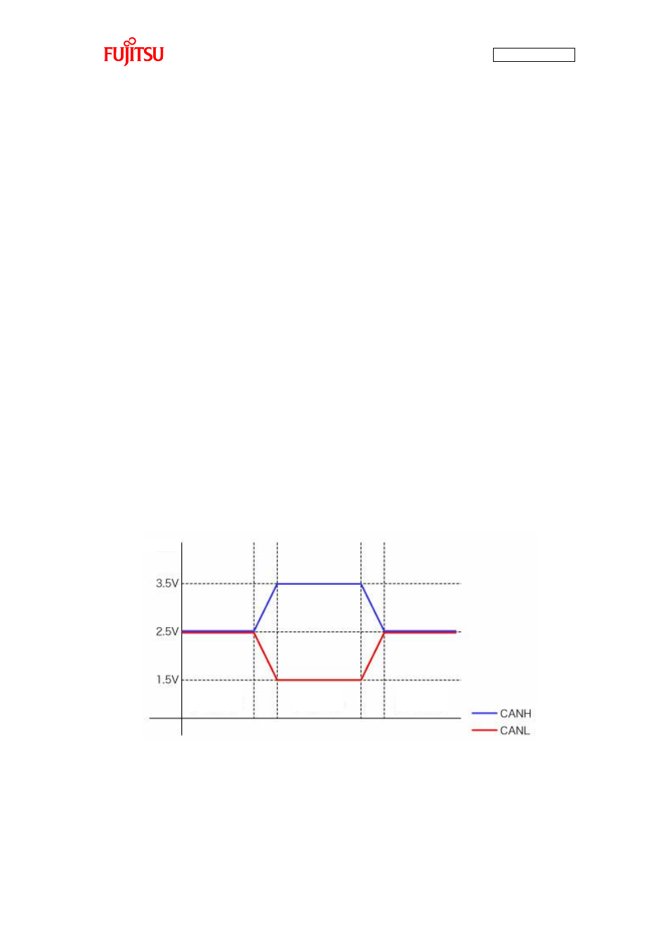
3. Differential transmission system
Taking account of influence from noise on the transmission paths, CAN employs the differential
transmission system in which the voltage difference between two signal lines is used to
determine “0”/”1”. The signal lines are respectively called CANH and CANL and the voltage
difference between them is used to determine the bus level. The differential is used to determine
logical “0”/”1”. As shown in “Figure 5-2 CAN bus signal levels”, the bus status of logical “0” is
called dominant and the bus status of logical “1” is called recessive. The communicable distance
depends on the communication speed; in the case of 1M bits/sec, up to 40 m is allowed. This is
also specified by a regulation.
Figure 5-2 CAN bus signal levels
Voltage
Logical
“1”
Recessive
Logical
“1”
Recessive
Logical
“0”
Dominant